Chapter 2 Installation
Mini-Convectron Module Instruction Manual - 275513 17
Length of tubing depends on the application. Longer tubing will affect vacuum pressure limit and
response time.
• Do not locate the module near the pump, where gauge pressure might be lower than normal
vacuum chamber pressure.
• Do not locate the module near a gas inlet or other source of contamination, where inflow of gas
or particulates causes atmospheric pressure to be higher than system atmosphere.
• Do not locate the module where it will be exposed to corrosive gases such as mercury vapor or
fluorine.
• Do not locate the module where it will vibrate. Vibration causes convection cooling, resulting in
inaccurate high pressure readings.
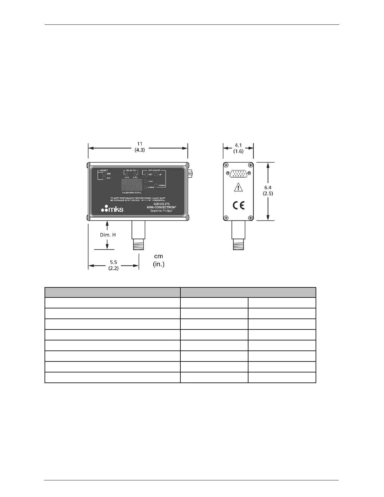
Figure 2-3 Mini-Convectron Module Dimensions
2.3.1.2 Orient the Module
For proper operation of the module above 1 Torr, orient the module so the axis is horizontal (see
Figure 2-4). Although the Convectron gauge will read correctly below 1 Torr with the module
mounted in any position, inaccurate readings will result at pressures above 1 Torr if the module axis
is not horizontal.
Table 2-1 Mini-Convectron Vacuum Connections
Vacuum Connections Dim. H
cm in.
1/8 NPT pipe thread, ½-inch inside diameter 2.2 0.9
1/4-inch 4 VCR
®
type fitting, female 3.0 1.2
1/2-inch 8 VCR type fitting, female 3.9 1.5
NW16KF flange 3.1 1.2
NW25KF flange 3.1 1.2
1.33-inch (NW16CF) ConFlat
®
flange 3.8 1.5
2.75-inch (NW35CF) ConFlat flange 3.8 1.5

 Loading...