Mini-Convectron Module Instruction Manual - 275513 57
Appendix B Theory of Operation
The module measures gas pressures from 1 x 10
–4
Torr to 1000 Torr. Vacuum chamber pressure is
measured by a Convectron convection-enhanced Pirani heat-loss gauge.
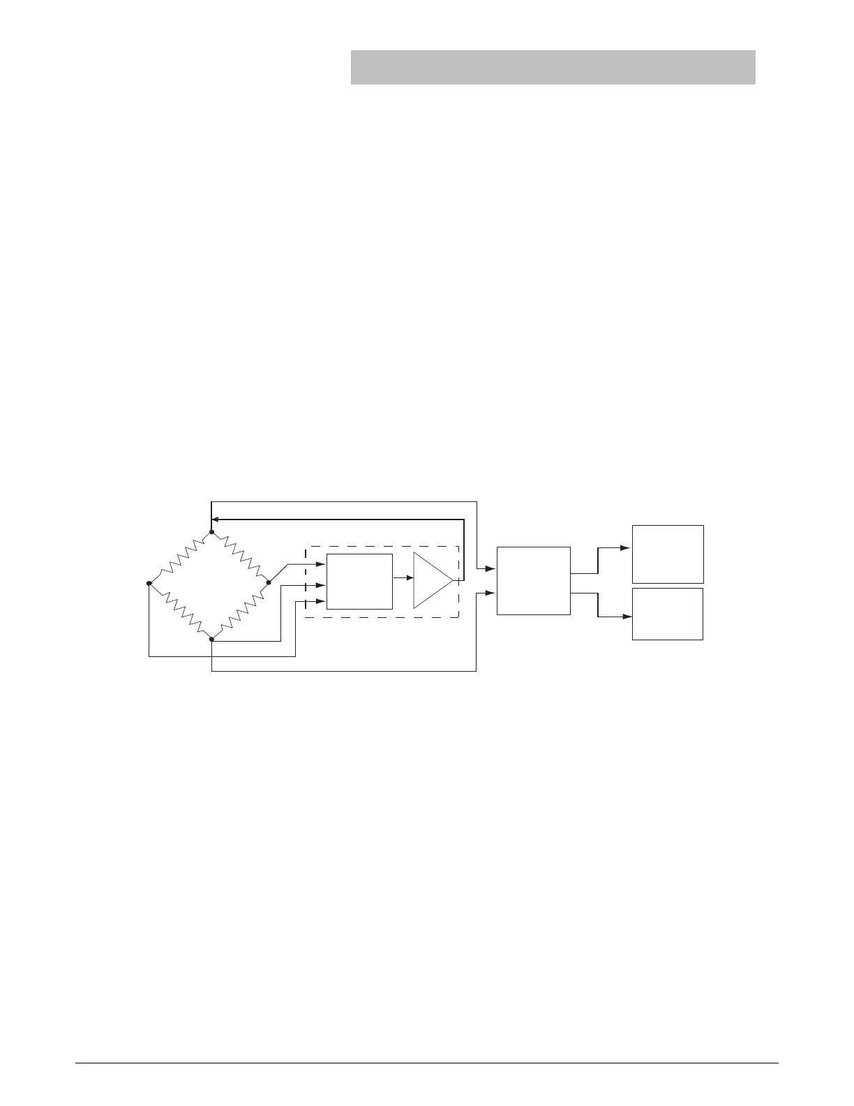
The Convectron gauge operates like a standard Pirani gauge, which employs the principle of a
Wheatstone bridge to convert pressure to voltage, but uses convection cooling to enable accurate
pressure measurement, when properly calibrated, from 10
–4
to 1000 Torr.
The sensing wire is an ultra-fine strand of gold-plated tungsten or solid platinum. The heated sensing
wire loses more heat as the ambient gas pressure increases. The more molecules contact the sensing
wire, the more power is required to keep the sensing wire at a constant temperature. So, as pressure
increases, the voltage across the Wheatstone bridge also increases.
The Convectron gauge has a temperature compensator, which causes bridge voltage to remain
unaffected by changes in ambient temperature.
The Convectron gauge sensing wire is designated R
1
in the Wheatstone bridge circuit. The
temperature compensator is designated R
2
. At bridge null, the following equation applies:
Bridge voltage is a non-linear function of pressure. This relationship is illustrated in Figure . If the
ambient temperature does not change, R
1
remains constant.
Wheatstone Bridge Diagram
As vacuum chamber pressure decreases, the number of molecules in the vacuum chamber and the
resulting heat loss from the sensing wire also decrease. Temperature and R
1
resistance therefore
increase.
The increased resistance through R
1
causes the bridge to become unbalanced and a voltage to
develop across the null terminals. The bridge controller senses the null voltage and decreases the
voltage across the bridge until the null voltage again equals zero. When the bridge voltage decreases,
the power dissipation in the sensing wire decreases, causing R
1
resistance to decrease to its previous
value.
A pressure increase causes an opposing series of occurrences, during which the bridge controller
increases the bridge voltage to maintain a zero null voltage.
R
1
R
2
R
3
+
R
4
-------------------=
Vacuum
and ATM
adjust
Process
control
Vacuum
output
Amplifier
Buffer
Bridge Control
R1 R3
R4 R2

 Loading...