Chapter 3
28 Mini-Convectron Module Instruction Manual - 275513
3.2 Nonlinear Analog Output
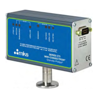
The module contains a convection-enhanced Pirani thermal conductivity gauge. The gauge
measures the heat loss from a heated sensing wire that is maintained at a constant temperature.
The analog output produces a nonlinear voltage that corresponds to measured pressure. Output
voltage is measured across pins 5 and 8 if the module has one setpoint relay or across pins 5 and 6
if the module has zero or two setpoint relays.
Refer to Table 3-6 to calculate pressure (y) as a function of output voltage (x). Figure 3-4 and
Figure 3-5 are graphs that represent true pressure for N
2
or air (y axis) versus voltage (x axis).
• Output impedance is 100 Ω.
• The output is normalized to 0.375 Vdc at vacuum chamber pressure and to 5.534 Vdc at 760
Torr (133.3 kPa, 1333 mbar) for N
2
or air.
The vacuum chamber pressure indicated by the gauge depends on the gas type, gas density
(pressure), and the module orientation. The module is factory calibrated for N
2
(air has approximately
the same calibration). For gases other than N
2
or air, heat loss varies at any given pressure, and you
must apply an appropriate conversion factor.
3.2.1 Commonly used Gases Other than N
2
or Air
Refer to Table 3-7 for pressure versus output voltage for 10 commonly used process gases other than
N
2
or air.
Refer to Figure 3-6, Figure 3-7, or Figure 3-8 to determine true pressure versus indicated pressure for
the gas that is being used.
3.2.2 Other Gases
If the gas being used is not included in Table 3-7, or for a gas mixture, you will need to generate a
calibration curve using a gas-independent transfer standard such as a capacitance manometer. Use
the following equation to determine the maximum usable output voltage:
Maximum usable output voltage = input voltage -4 Vdc

 Loading...