36
8-504.11
TROUBLESHOOTING
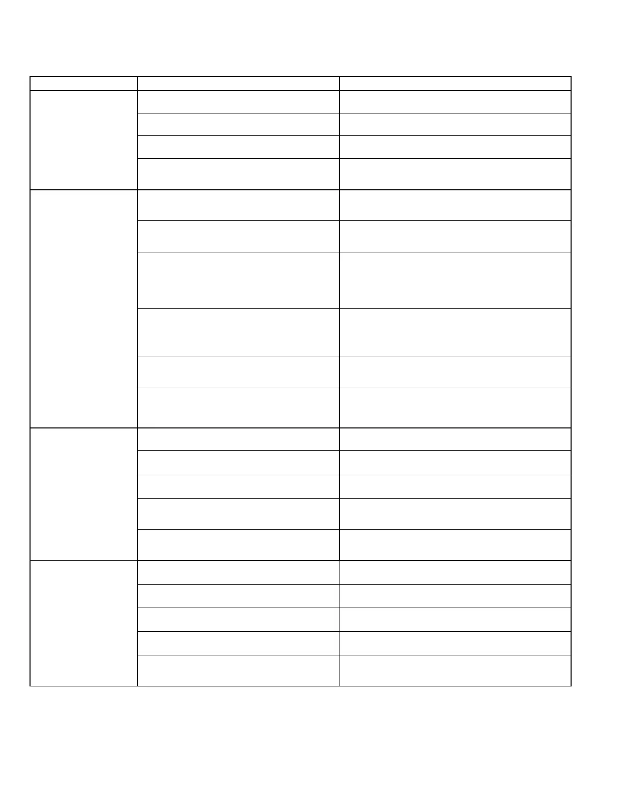
Table 36.1 - Troubleshooting – Indoor Unit
Trouble Possible Cause Possible Remedy
A. Two LED Flashing
(Microprocessor units
only Digit 8 = M)
1. Faulty oat switch. (Connected to micro terminals
‘T4’)
1. See section "F. Condensate High Level (microprocessor
units: LED’s will ash)".
2. Fan thermal trip. (Connected to micro terminals
‘T4’)
2. See section "C. Fans Will Not Run".
3. Freeze stat alarm. (Connected to micro terminals
‘T4’)
3. See section "G. Coil Freeze".
4. Return air sensor failure.
(Connected to micro terminals ‘T1’)
4. Use the unit wiring schematic to isolate the return air
sensor and measure the resistance. Sensor is 50K@72°F
type. Check and replace if necessary.
B. Unit Will Not Operate
1. No power mains power.
1. Check power supply to the unit. For microprocessor units
(Digit 8 =M), check power to the microprocessor and
check the on-board micro fuse.
2. No 24V control circuit power.
2. Check the 24V feed from the control transformer. If not
present, check transformer windings – replace if
necessary.
3. Control circuit disabled by unit protection device.
3. In some models, particularly electro-mechanical units
(Digit 8 = E), some protection devices (such as freeze-
stats, fan trips, etc) are wired in line with the 24V control
circuit feed to cause the unit to shut down in an alarm
condition. Use the unit’s wiring schematic to identify these
devices and investigate accordingly.
4. Infrared receiver failure. (Microprocessor units
only - Digit 8 = M)
4. If the green LED is lit or ashing, receiver is OK. If there
are no LEDs lit and the unit will not respond to the
transmitter, press the On/O button on the fascia display
panel. If the unit responds to the On/O button receiver is
OK. Check transmitter.
5. Transmitter failure. (Microprocessor units only -
Digit 8 = M)
5. Try new batteries rst. If no response press On/O button
on unit fascia. If the unit responds to the On/O button
transmitter is faulty.
6. Microprocessor failure. (Microprocessor units only
- Digit 8 = M)
6. The microprocessor is the least likely component to be at
fault. Investigate all other possibilities in every section of
this troubleshooting guide rst. Replace the micro only
after all other avenues of investigation are exhausted.
C. Fans Will Not Run
1. Loose wire.
1. Check all fan wire connections. Use unit’s electrical
schematic to verify that fan is wired correctly.
2. Faulty fan capacitor. 2. Check fan capacitors, replace if necessary.
3. Faulty fan motor.
3. Check fan motor protector for open circuit, replace if
necessary.
4. Fan thermal trip
4. Motor temperature limits exceeded, temp cutout is 150⁰C±
5⁰C. Check fan motor protector for open circuit, replace if
necessary.
5. Faulty PC Board.
5. On electro-mechanical units check for a signal at “G”
terminal. On microprocessor units check for steady green
light on display panel.
D. No Cooling
1. Incorrect MODE setting. (Microprocessor units
only - Digit 8 = M)
1. Check that the transmitter MODE is set to Cooling or Auto
Mode.
2. Set point too high.
2. Check the set point on the transmitter or wall mounted
thermostat and adjust if necessary.
3. Compressor protection delay. (Electro-mechanical
DX units only - Digit 2,3 = SD or SH & Digit 8 = E)
3. Wait for ten minutes and then re-check if cooling is
operating.
4. Dirty or blocked air lter. 4. See section "G. Coil Freeze".
5. High condensate level trip.
5. Drain the condensate tray and investigate. See section
"F. Condensate High Level (microprocessor units: LED’s
will ash)".