Mounting
31
05/01 AWB2700-1384GB
3
Step 6
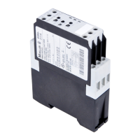
The electronics module must be secured onto the base element
using the locking clips. To perform this, place a screwdriver in the
middle of the right-hand locking clip, and push the slide to the left.
Push the slide of the left-hand locking clip to the right.
The electronics module is now locked onto the base element and
can only be removed when both locking clips are unlocked (see
Dismounting a single Base-Element, Step 2).
Step 7
The wiring of I/O-points is established via the proven tension clamp
principle. Insert a screwdriver into the rectangular opening and
press it in until it comes up against a stop. By doing so, the tension
clamp is opened, thus allowing the wiring to be inserted. Then, pull
out the screwdriver. The tension clamp is closed again, the wiring
is complete.
The - potential as well as the + potential of distribution rails are
connected to each other automatically via an integrated shorting
link. Distribution rails of the base element can be removed. If a
distribution rail becomes loose, refit it by simply plugging it back
onto the carrier.
 Loading...