– 8 –
∗
∗∗
∗86 Cancel Verify Keypad Display [1]
0 = no; 1 = yes
This feature causes a “ALARM CANCELED” display on the
LCD keypad under the following conditions:
• After the kissoff of the cancel message to the Central
Station, indicating a successful transmission.
• When an alarm is successfully canceled before the
Central Station received the Alarm message. E.g., if an
alarm is incorrectly triggered and the user presses code +
OFF before the dial delay time has expired, the message
will never go out to the CS.
•
When the Cancel report is not enabled and the system is
disarmed:
a. before dialer delay expires (alarm report not sent)
message “Alarm Canceled” is displayed.
b. after dialer delay expires message “Alarm Canceled”
is not displayed
.
∗
∗∗
∗87 Misc. Fault Delay Time [0]
(used with Configurable Zone Types “digit 6”)
0 = 15 seconds 6 = 2-1/2 min #+12 = 8 min
1 = 30 seconds 7 = 3 min #+13 = 10 min
2 = 45 seconds 8 = 4 min #+14 = 12 min
3 = 60 seconds 9 = 5 min #+15 = 15 min
4 = 90 seconds #+10 = 6 min
5 = 2 minutes #+11 = 7 min
UL: may only be used on non-burglar alarm/ non-fire alarm
zones when used in fire and/or UL burglar alarm installation
Used with zones assigned to a configurable zone type with fault
delay on (configurable zone type digit “6”), and sets a zone
response time of 15 seconds to 15 min. It can be assigned to
zones with sensors that provide a trouble indication when an oil
tank is low, or similar applications for critical condition
monitoring where non-alarm response is desired.
∗
∗∗
∗88 Program Mode Lockout Options [0]
0 = standard *98 installer code lockout (reentry only by [∗] +
[#] within 50 seconds after power up)
1 = lockout [∗] + [#] reentry after *98 exit (reenter via
installer code or downloader only)
2 = lockout all local programming after *98 exit (reentry via
downloader only)
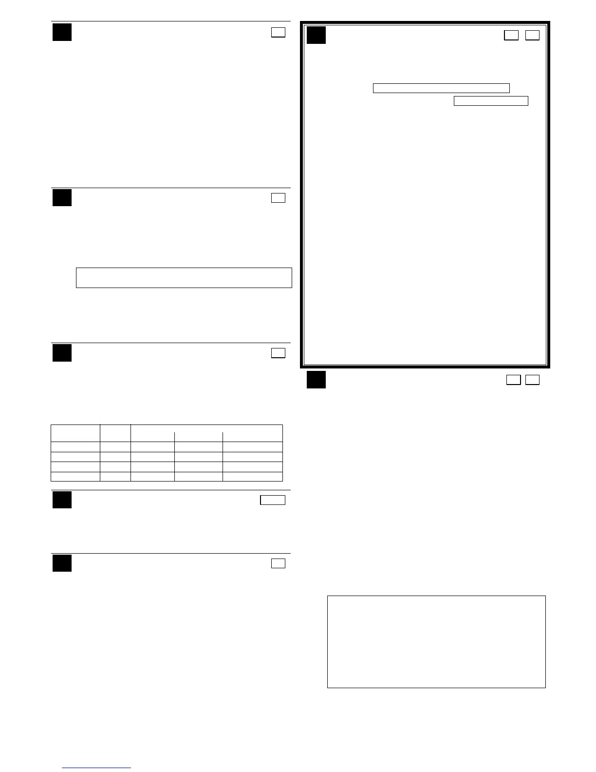
This table summarizes the Program Mode Lockout options:
Exit *88 Reentry By:
Command Entry Installer Power-up† Downloader
*99 n/a yes yes yes
*98 0 no yes yes
*98 1 yes no yes
*98 2 no no yes
† pressing [∗] + [#] within 50 seconds of power up
∗
∗∗
∗89 Event Log Full Report Code [00] |
See box above field *59 for report code entries.
If an Event Logging selection is made in field ∗90, a
message can be sent to the central station receiver when
the log is 80% full. If the log becomes full, new messages
overwrite the oldest messages in the log.
∗
∗∗
∗90 Event Log Enables [15]
NOTE
:
System messages are logged when any non-zero
entry is made. To select all options, enter #15.
0 = None
1 = Alarm/Alarm Restore
2 = Trouble/Trouble Restore
4 = Bypass/Bypass Restore
8 = Open/Close.
Example:
To select “Alarm/Alarm
Restore”, and “Open/Close”, enter 9 (1 + 8);
This system can record various events in a history log
(VISTA-20PMT = 100 events; VISTA15PMT = 50 events). At
any time, the downloader operator can then upload the log
and view or print out all or selected categories of the log, or
can clear the log. Event log can also be viewed at an alpha
keypad. The display/printout at the central station will show
the date, time, event, and description of the occurrences.
Data Entry Example: To select Alarm/Alarm Restore” and
“Open/Close”, enter 9 (1+ 8); to select all events, enter #15.
NOTE
:
System messages are logged when any non-zero
entry is made.
∗
∗∗
∗91 Option Selection / Remote [8, 0]
Interactive Services (RIS) Enable 1 2
Entry 1: Options
0 = None
1 = Bell Supervision Processing
4 = AAV UL: must use ADEMCO UVCM module
8 = Exit Delay Restart/Reset
††
UL: must be disabled
#+12 = AAV and Exit Delay Restart/Reset
SIA Guidelines: Exit Delay should be enabled.
Entry 2: Call Waiting Disable / RIS Enable
0 = call waiting not used
1 = call waiting disable digits (*70) entered in field *40;
(when selected, the system dials the entry in field *40
only on alternate dial attempts; this allows proper
dialing in the event call waiting service is later
canceled by the user).
2 = RIS (Remote Interactive Services) enabled
3 = Call Waiting disable and RIS enabled
IMPORTANT: AAV should not be used when Paging or
Alarm Reports are sent to a secondary number unless the
monitoring zone option is used (which pauses calls).
Otherwise, the call to the secondary number by the
communicator after the alarm report will prevent the AAV
from taking control of the telephone line, and the AAV
“Listen in” session cannot take place.
††“Exit Delay Restart/reset” option allows use of the [∗] key
to restart the exit delay at any time when the system is
armed STAY or INSTANT. This feature also enables
automatic exit delay reset, which resets exit delay if the
entry/exit door is re-opened and closed before exit delay
time expires after arming AWAY. Automatic Exit Delay
Reset occurs only once during an armed AWAY period.
Remote Interactive Services (RIS) Enable: This option
enables enhanced Remote Interactive Services (RIS), if
supported by the communication service in use.
∗
∗∗
∗92 Phone Line Monitor Enable [0,0]
Entry 1: 1 2
0 = disabled, 1-15 = 1 min - 15 min
(#+10 = 10 min; #+11 = 11 min; #+12 = 12 min; #+13 = 13
min; #+14 = 14 min; #+15 = 15 min)
Entry 2:
0 = Keypad display when line is faulted
1 = Keypad display plus keypad trouble sound
2 = Same as “1”, plus programmed output device STARTS.
If either partition is armed, external sounder activates
also.
NOTE: Output Device must either be programmed to be
STOPPED in field ✱80 or STOPPED by Code + # + 8 +
output number.
Entry 1: Sets the length of time a phone line fault must
remain after detected before the second digit option is
activated.
Entry 2: Selects the desired phone line fault response.
Option 2 may be used even if a relay unit or Powerline
carrier device is not connected to the control.
Programmed Output Device must either be programmed to
be STOPPED in field ∗80 or STOPPED by entry of [security
code] + [#] + 8 + device number. Partition in ∗80 should be
set to “0,” for STOP.
UL: Field *92 must be enabled for fire alarm installations,
UL commercial burglar alarm installations and UL
residential burglar alarm installations.
If the control unit is used on a UL commercial burglar alarm
system which requires 2 methods of remote
communication, then the control unit’s DACT and the other
method of signal transmission must monitor each other
against communication failure and line fault. The fault must
be received and annunciated within 200 seconds of its
occurrence.