EasyManua.ls Logo

Mooney M20R - Allowable Free-Play Limits; Elevator System; Rudder Rigging and Adjustments; Rudder Torque Tube Removal

Default Icon
360 pages
Print Icon
To Next Page IconTo Next Page
To Previous Page IconTo Previous Page
Loading...
MOONEY
AIRCRAFT
CORPORATION
M20R
SERVICE
AND
MAINTENANCE
MANUAL
-3D
C
D
~I
9’
SMX27-8
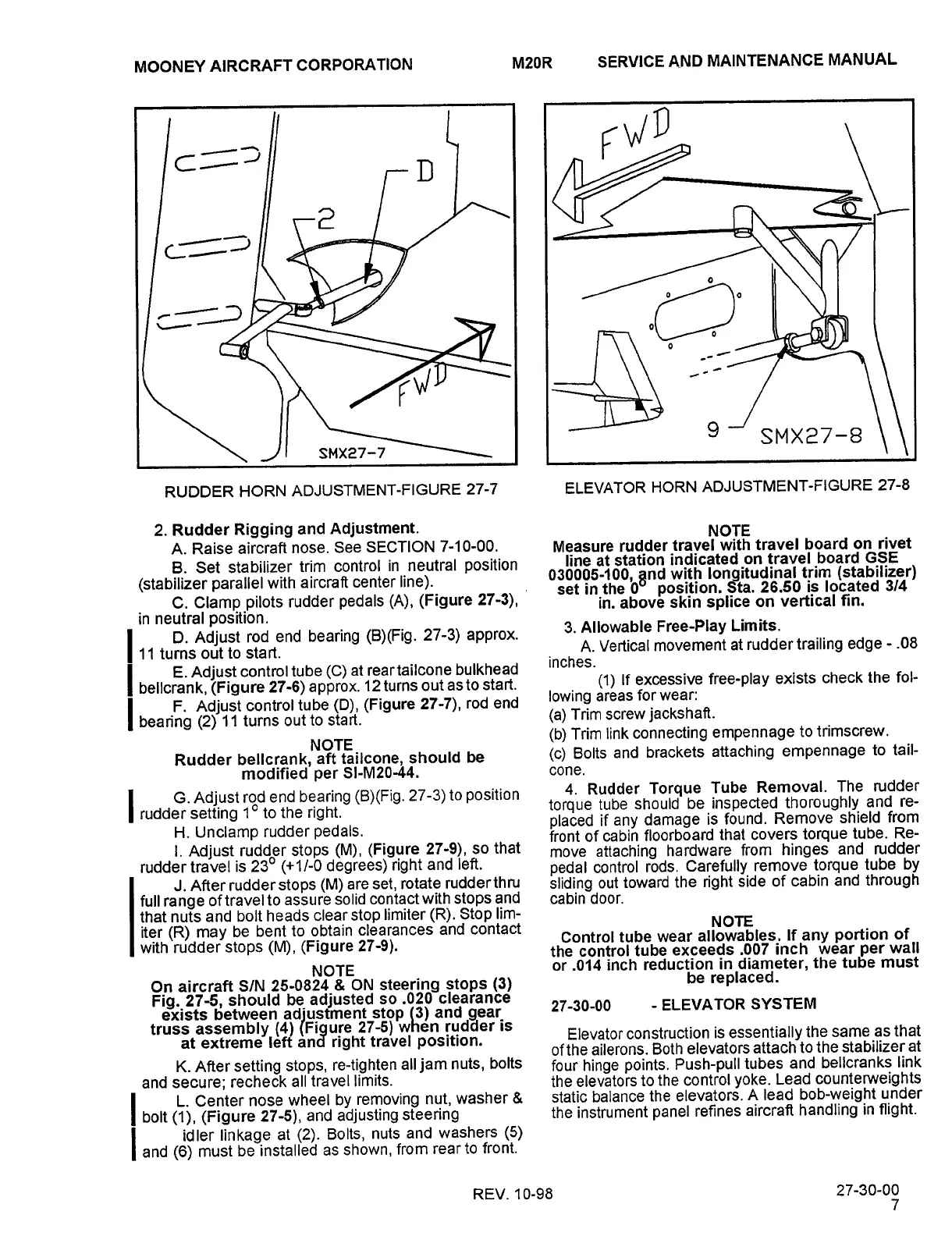
SMX27-7
RUDDER
HORN
ADJUSTMENT-FIGURE
27-7
ELEVATOR
HORN
ADJUSTMENT-FIGURE
27-8
2.
Rudder
Rigging
and
Adjustment.
NOTE
A.
Raise
aircraft
nose.
See
SECTION
7-10-00.
Measure
rudder
travel
with
travel
board
on
rivet
8.
Set
stabilizer
trim
control
in
neutral
position
line
at
station
indicated
on
travel
board
GSE
030005-100,
gnd
with
longitudinal
trim
(stabilizer)
(stabilizer
parallel
with
aircraft
center
line).
set
in
the
0
position.
Sta.
26.50
is
located
3/4
C.
Clamp
pilots
rudder
pedals
(A),
(Figure
27-3),
in.
above
skin
splice
on
vertical
fin.
in
neutral
position.
3.
Allowable
Free-Play
Limits.
I
D.
Adjust
rod
end
bearing
(B)(Fig.
27-3)
approx.
inches.A.
Vertical
movement
at
rudder
trailing
edge
.08
11
turns
out
to
start.
I
E.
Adjust
control
tube
(C)
at
reartailcone
bulkhead
belicrank,
(Figure
27-6)
approx.
12
turns
out
as
to
start.
(1)
If
excessive
free-play
exists
check
the
fol-
I
F.
Adjustcontrol
tube
(D),
(Figure
27-7),
rod
end
lowing
areas
for
wear:
bearing
(2)
11
turns
out
to
start.
(a)
Trim
screw
jackshaft.
(b)
Trim
link
connecting
empennage
to
trimscrew.
NOTE
(c)
Bolts
and
brackets
attaching
empennage
to
tail-
Rudder
bellcrank,
aft
tailcone,
should
be
modified
per
SI-M20-44.
cone.
I
G.Adjustrod
end
bearing
(B)(FIg.
27-3)
to
position
4.
Rudder
Torque
Tube
Removal.
The
rudder
torque
tube
should
be
inspected
thoroughly
and
re-
rudder
setting
1"
to
the
right.
placed
if
any
damage
is
found.
Remove
shield
from
H.
Unclamp
rudder
pedals.
front
of
cabin
floorboard
that
covers
torque
tube.
Re-
i.
Adjust
rudder
stops
(M),
(Figure
27-9),
so
that
move
attaching
hardware
from
hinges
and
rudder
rudder
travel
is
230
(+1/-0
degrees)
right
and
left,
pedal
control
rods.
Carefully
remove
torque
tube
by
J.
After
rudder
stops
(M)
are
set,
rotate
rudderthru
sliding
out
toward
the
right
Side
of
cabin
and
through
full
range
of
travel
to
assure
solid
contact
with
stops
and
cabin
door.
that
nurs
and
bolt
heads
clear
stop
limiter
(R).
Stop
lim-
NOTE
iter
(R)
may
be
bent
to
obtain
clearances
and
contact
Control
tube
wear
allowables.
If
any
portion
of
with
rudder
stops
(M),
(Figure
27-9).
the
control
tube
exceeds
.007
inch
wear
per
wall
NOTE
or.014
inch
reduction
in
diameter,
the
tube
must
On
aircraft
S/N
25-0824
8
ON
steering
stops
(3)
be
replaced.
Fig.~27-5,
should
be
adjusted
so.020clearance
27-30-00
ELEVATOR
SYSTEM
exists
between
adjustment
stop
(3)
and
truss
assembly~(4)
(i-lgure
27-5)~when
rudder
is
Elevator
construction
is
essentially
the
same
as
that
at
extreme
left
and
right
travel
position.
of
the
ailerons.
Both
elevators
attach
to
the
stabilizer
at
K.
After
setting
stops,
re-tighten
all
jam
nuts,
bolts
four
hinge
points.
Push-pull
tubes
and
bellcranks
link
and
secure;
recheck
all
travel
limits.
the
elevators
to
the
control
yoke.
Lead
counterweights
L.
Center
nose
wheel
by
removing
nut,
washer
8
static
balance
the
elevators.
A
lead
bob-weight
under
I
bolt
(1),
(Figure
27-5),
and
adjusting
steering
the
instrument
panel
refines
aircraft
handling
in
flight.
la,,
idler
linkage
at
(2).
Bolts,
nuts
and
washers
(5)
(6)
must
be
installed
as
shown,
from
rear
to
front.
REV.
10-98
27-30-0~
Island Enterprises

Table of Contents