EasyManua.ls Logo

Mooney M20R - Main Gear Installation; Main Gear Door Rigging

Default Icon
360 pages
Print Icon
To Next Page IconTo Next Page
To Previous Page IconTo Previous Page
Loading...
SERVICE
AND
MAINTENANCE
MANUAL
M20R
MOONEY
AIRCRAFT
CORPORATION
11.
identify
all
components
removed,
and
DOi
NOT
rigging
procedures
should
be
used
when
reinstalling
inter-mix
right
and
left
gear
components,
them:
12.
DO
NOT
attempt
to
repair
any
heat
treated
com-
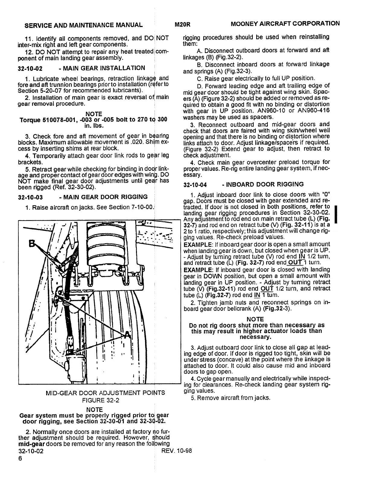
A.
Disconnect
outboard
doors
at
forward
and
aft
ponent
of
main
landing
gear
assembly.
linkages
(B)
(Fig.32-2).
B.
Disconnect
inboard
doors
at
forward
linkage
32-10-02
MAIN
GEAR
INSTALLATION
1.
Lubricate
wheel
bearings,
retraction
linItage
and
and
springs
(A)
(Fig.32-3).
C.
Raise
gear
electrically
to
full
UP
position.
fore
and
aft
trunnion
bearings
priorto
installation
(ntferto
D.
FoMrard
leading
edge
and
aft
trailing
edge
of
Section
5-20-07
for
recommended
lubricants).
mid
gear
door
should
be
tight
against
wing
skin.
Spac-
2.
Installation
of
main
gear
is
exact
reversal
of/
main
ers
(A)
(Figure
32-2)
should
be
added
or
removed
as
re-
gear
removal
procedure.
quired
to
obtain
a
good
fit
with
no
binding
or
distortion
NOTE
with
gear
in
UP
position.
AN960-10
or
AN960-416
Torque
510078-001,
-003
or
-005
bolt
to
270
tci
300
washers
may
be
used
as
spacers.
in.
Ibs.
3.
Reconnect
outboard
and
mid-gear
doors
and
check
that
doors
are
faired
with
wing
skin/wheel
well
3.
Check
fore
and
aft
movement
of
gear
in
b~aring
opening
and
that
there
is
no
binding
ordigtortion
where
blocks.
Maximum
allowable
movement
is
.020.
Shl’m
ex-
links
attach
to
door.
Adjust
linkage/space‘rs
if
required.
cess
by
inserting
shims
at
rear
block.
(Figure
32-2)
Extend
gear
to
adjust,
then
retract
to
4.
Temporarily
attach
gear
door
link
rods
to
ge~r
leg
check
adjustment.
brackets.
4.
Check
main
gear
overcenter
preload
torque
for
5.
Retract
gear
while
checking
for
binding
in
doo/r
link-
proper
values.
Re-rig
entire
landing
gear
system,
if
nec-
age
and
proper
contact
of
gea
r
door
edges
with
winjl.
DO
essary.
NOT
make
final
gear
door
adjustments
until
gedr
has
been
rigged
(Ref.
32-30-02).
32-10-04
INBOARD
DOOR
RIGGING
32-10-03
MAIN
GEAR
DOOR
RIGGING
1.
Adjust
inboard
door
link
to
close
doors
with
"O"
gap.
Doors
must
be
closed
with
gear
extended
and
re-
i.
Raise
aircraft
on
jacks.
See
Section
7-10-00.
tracted.
If
door
is
not
closed
in
both
positions,
refer
to
I
landing
gear
rigging
procedures
in
Section
32-30-02.
Any
adjustment
to
rod
end
on
main
retract
tube
(L)
(Fig.
32-7)
and
rod
end
on
retract
tube
(V)
(Fig.
32-11)
is
at
a
C~
2
to
1
ratio,
respectively;
this
adjustment
will
change
rig-
t:
ging
values.
Re-check
preload
values.
EXAMPLE:
If
inboard
gear
door
is
open
a
small
amount
when
landing
gear
is
down,
but
closed
when
gear
is
UP.
Adjust
by
turning
retract
tube
(V)
rod
end
IN
1/2
turn,
and
retract
tube
(L)
(Fig.
32-7)
rod
end
OUT
1
turn.
EXAMPLE:
If
inboard
gear
door
is
closed
with
landing
gear
in
DOWN
position,
but
open
a
small
amount
with
ii
tube
(V)
(Fig.32-11)
rod
end
OUT
1/2
turn,
and
retract
landing
gear
in
UP
position.
Adjust
by
turning
retract
tube
(L)
(Fig.32-7)
rod
end
IN
1
tum.
2.
Tighten
jamb
nuts
and
reconnect
springs
on
in-
I
board
gear
door
bellcrank
(A)
(Fig.32-3).
NOTE
I
Do
not
rig
doors
shut
more
than
necessary
as
I
i
this
may
result
in
higher
actuator
loads
than
I.
necessary.
II
3.
Adjust
outboard
door
link
to
close
all
gap
at
lead-
II
i.
ingedgeofdoor.
If
door
is
rigged
too
tig
ht,
skin
will
be
under
stress
(concave)
at
the
point
where
the
linkage
is
attached
to
door.
It
could
also
cause
mid
and
inboard
i
i
doors
to
gap
open.
4.
Cycle
gear
manually
and
electrically
while
inspect-
ing
forclearances.
Re-check
landing
gear
system
rig-
MID-GEAR
DOOR
ADJUSTMENT
POINTS
ging
values.
FIGURE
32-2
5.
Remove
aircraft
from
jacks.
NOTE
Gear
system
must
be
properly
rigged
prior
to
gear
door
rigging,
see
Section
32-30-01
and
32-3C)-02.
2.
Normally
once
doors
are
installed
at
factory
6o
fur-
ther
adjustment
should
be
required.
However,
should
mid-gear
doors
be
removed
for
any
reason
the
foll’owing
32-1
0-02
REV.
10-98
Island Enterprises

Table of Contents