EasyManua.ls Logo

Mooney M20R - Dents; Repairs for Welded Assemblies; Split-Sleeve Splice Diagram; Tension Fitting Replacement

Default Icon
360 pages
Print Icon
To Next Page IconTo Next Page
To Previous Page IconTo Previous Page
Loading...
MOONEY
AIRCRAFT
CORPORATION
M20R
SERVICE
AND
MAINTENANCE
MANUAL
C.
Select
a
tube
with
an
outer
diameter
equal
to
F.
Install
replacement
tube
over
inner
sleeve
al-
inner
diameter
of
tube
to
be
repaired
and
with
same
lowing
a
1/8
inch
gap
for
welding
between
original
and
replacement
tubes.
wallthickness.
G.
Weld
inner
sleeve
to
tube
stubs
through
the
D.
Cut
tube
to
length,
five
times
outer
diameter
of
1/8
inch
gap,
forming
an
overlayed
bead
across
gap.
tube
to
be
spliced.
H.
Rosette
weld
replacement
tube
to
inner
sleeve
E.
Install
inner
sleeve
in
tube
to
be
repaired
so
in
two
or
more
places.
that
its
outer
end
is
one
and
one-half
of
original
tube
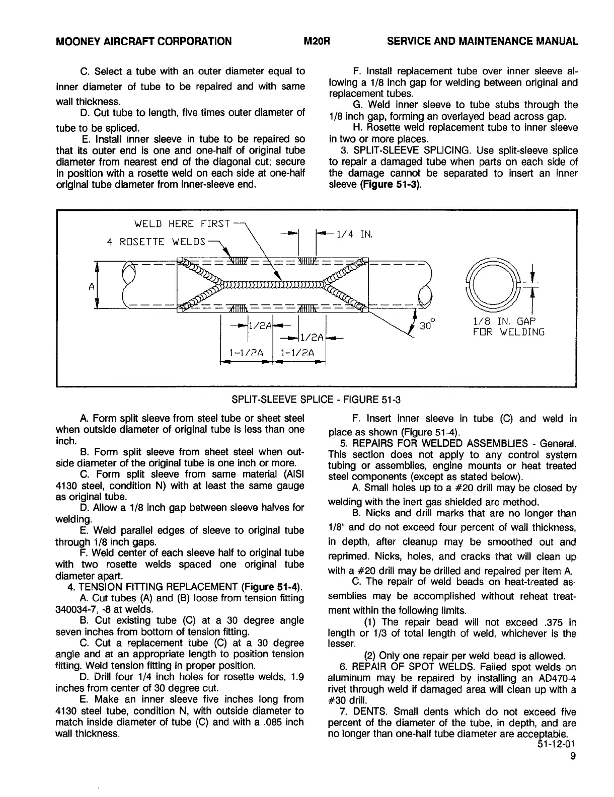
3.
SPLIT-SLEEVE
SPLICING.
Use
split-sleeve!
splice
diameter
from
nearest
end
of
the
diagonal
cut;
secure
to
repair
a
damaged
tube
when
parts
on
each
side
of
in
position
with
a
rosette
weld
on
each
side
at
one-half
the
damage
cannot
be
separated
to
insert
an
inner
original
tube
diameter
from
inner-sleeve
end.
sleeve
(Figure
51-3).
WELD
HERE
FIRST
t
ROSLITL
WELOS?
-1
IC1/1IN
4
-f
FOR
WELDING
300
1/8
IN,
GAP
1-1/2A1-1/2A
SPLIT-SLEEVE
SPLICE
FIGURE
51-3
A.
Form
split
sleeve
from
steel
tube
or
sheet
steel
F.
Insert
inner
sleeve
in
tube
(C)
and
weld
in
when
outside
diameter
of
original
tube
is
less
than
one
place
as
shown
(Figure
51-4).
inch.
5.
REPAIRS
FOR
WELDED
ASSEMBLIES
General.
B.
Form
split
sleeve
from
sheet
steel
when
out-
This
section
does
not
apply
to
any
control
system
side
diameter
of
the
original
tube
is
one
inch
or
more.
tubing
or
assemblies,
engine
mounts
or
heat
treated
C.
Form
split
sleeve
from
same
material
(AIS[
steel
components
(except
as
stated
below).
4130
steel,
condition
N)
with
at
least
the
same
gauge
A.
Small
holes
up
to
a
#20
drill
may
be
csosed
by
as
original
tube.
weeding
with
the
inert
gas
shielded
are
method.
D.
Allow
a
1/8
inch
gap
between
sleevehalves
for
B.
Nicks
and
drill
marks
that
are
no
longer
than
welding.
E.
Weld
parallel
edges
of
sleeve
to
original
tube
118"
and
do
not
exceed
four
percent
of
wall
thickness,
through
1/8
inch
gaps.
in
depth,
after
cleanup
may
be
smoothed
out
and
F.
Weld
center
of
each
sleeve
half
to
original
tube
reprimed.
Nicks,
holes,
and
cracks
that
wils
clean
up
with
two
rosette
welds
spaced
one
original
tube
diameter
apart.
with
a
#20
drill
may
be
drilled
and
repaired
per
item
A.
C.
The
repair
of
weld
beads
on
hed-treated
as-
4.
TENSION
FITTING
REPLACEMENT
(Figure
51-4).
A.
Cut
tubes
(A)
and
(B)
loose
from
tension
fitting
semblies
may
be
accomplished
without
reheat
treat-
340034-7,
-8
at
welds,
ment
within
the
following
limits.
B.
Cut
existing
tube
(C)
at
a
30
degree
angle
(1)
The
repair
bead
will
not
exceed
.375
ire
seven
inches
from
bottom
of
tension
fitting,
length
or
1/3
of
total
length
of
weld,
whichever
Is
the
C.
Cut
a
replacement
tube
(C)
at
a
30
degree
lesser.
angle
and
at
an
appropriate
length
to
position
tension
(2)
Only
one
repair
per
wesd
bead
is
allowed.
fitting.
Weld
tension
fitting
in
proper
position.
6.
REPAIR
OF
SPOT
WELDS.
Failed
spot
welds
on
D.
Drill
four
1/4
Inch
holes
for
rosette
welds,
1.9
aluminum
may
be
repaired
by
OnstaOlingan
8D47(a-41
inches
from
center
of
30
degree
cut.
rivet
through
weld
if
damaged
area
will
clean
up
with
a
E.
Make
an
inner
sleeve
five
inches
song
from
#30
csrils.
4130
steel
tube,
condition
N,
with
outside
diameter
to
7.
DENTS.
Small
dents
which
do
not
exceed
five
match
inside
diameter
of
tube
(C)
and
with
a
.085
inch
percent
of
the
diameter
of
the
tube,
in
depth,
and
are
wall
thickness.
no
songer
than
one-half
tube
diameter
are
acceptable.
51-%2-66
Island Enterprises

Table of Contents