EasyManua.ls Logo

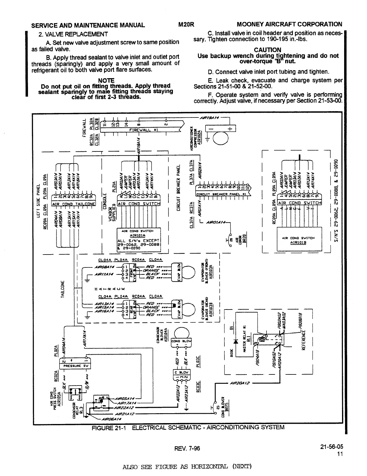
Mooney M20R - Electric Schematic - Air Conditioning System

Default Icon
360 pages
Print Icon
To Next Page IconTo Next Page
To Previous Page IconTo Previous Page
Loading...
SERVICE
AND
MAINTENANCE
MANUAL
MZOR
MOONN
Al
RC
RAFT
C
ORPORATION
2.
VALVE
REPLACEMENT
C.
Install
valve
in
coil
header
and
position
as
neces-
A.
Set
new
valve
adjustment
screw
to
same
position
sary.
Tighten
connection
to
19Q´•195
in.-lbs.
as
failed
valve.
CAUTION
B.
Apply
thread
sealant
to
valve
inlet
and
outlet
port
Use
backup
wrench
during
tightening
and
do
not
threads
(sparingly)
and
apply
a
very
small
amount
of
over-torque’8"
nut.
refrigerant
oil
to
both
valve
port
flare
surfaces.
D.
Connect
valve
inlet
port
tubing
and
tighten.
NOTE
E.
Leak
check,
evacuate
and
charge
system
per
Do
not
put
oil
on
fitting
threads.
Apply
thread
Sections
21-51-00
21-52-00.
sealant
sparingly
to
maTe
fitting
th~ads
staying
clear
of
first
2-3
threads.
F.
Operate
system
and
verify
valve
is
performing
correctly.
Adjust
valve,
if
necessa~y
per
Section
21-53-00.
FIREWALL
Y1
HIIA~gAN
Z
r
I
r
?t?t
22
B
~I
8%
~Iii
IB
I~
n
PaE*wra
8
i
i
,w,,
~IR
COND
SWI
g
aa
L
1~40/A
it
~I
11
711
%I
’1
Igl/
*II
CDND
fVITCH
alRIO1A
i
*la
COND
S/N’r
EXCEPT
~PIR1OIB
1
L
I
I~
_1
I
I-
I-
CLO~PLOill
e~
IAO11AII
BLACK
r
RL-B
X
W~
II
I
Il
I
CLOIA
PL04A
RC04A
CL04A
A~ytl
R~Z)
cl
r
81
11
BLACK
r
~wD
L
Y
~1
I
ar
~I
1
er~
81
i
ai,~w
,fi
g
sE~
1
Qg~l
~CPI
I~6PRMN
FIGURE
21-1
ELECTRICAL
SCHEMATIC
AIRCONDITIONING
SYSTEM
REV.
7-96
21-56-05
ALSO’
SEE
FIGURE
AS
HORIZONTAL
(NEZ~)
Island Enterprises

Table of Contents