EasyManua.ls Logo

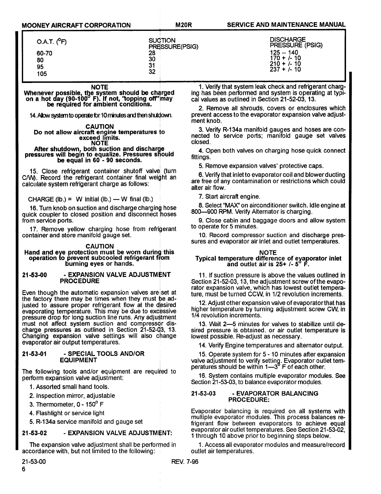
Mooney M20R - Evaporator Balancing Procedure; Expansion Valve Adjustment Procedure; Special Tools

Default Icon
360 pages
Print Icon
To Next Page IconTo Next Page
To Previous Page IconTo Previous Page
Loading...
MOONEY
AIRCRAFT
CORPORATION
M20R
SERVICE
AND
MAINTENANCE
MANUAL
O.A.T.
eF)
SUCTION
DISCHARGE
PREISSURE(PSIG)
PRESSURE
(PSIG)
60-70
28
125 140
80
30
170
10
95
31
210
10
105
32
237
10
NOTE
1.
Verify
that
system
leak
check
and
refrigerant
charg-
Whenever
possible,
the
system
should
be
ch~rged
ing
has
been
performed
and
system
is
operating
at
typi-
on
a
hot
day
(90-100’
Fl.
If
not,
’topping
off’lmay
cat
values
as
outlined
in
Section
21-52-03,
13.
be
required
for
ambient
conditions.
2.
Remove
all
shrouds,
covers
or
enclosures
which
14.
Allow
system
to
operate
forl0
minLAes
and
then
ShlRdOlhlll.
prevent
access
to
the
evaporator
expansion
valve
adjust-
ment
knob.
CAUTION
Do
not
allow
aircraft
engine
temperatures
to
3.
Verify
R-134a
manifold
gauges
and
hoses
are
con-
exceed
Ilmits.
nected
to
service
ports;
manifold
gauge
set
valves
NOTE
closed.
After
shutdown
both
suction
and
discharde
4.
Open
both
valves
on
charging
hose
quick
connect
pressures
will
~gln
to
equalize.
Pressures
s9ould
fittings.
be
equal
in
60
90
seconds.
15.
Close
refrigerant
container
shutoff
valvel
(turn
5.
Remove
expansion
valves’
protective
caps.
CNV).
Record
the
refrigerant
container
final
weight
an
6.
Verify
that
inlet
to
evapo
rater
coil
and
blower
d
ucting
calculate
system
refrigerant
charge
as
follows:
are
free
of
any
contamination
or
restrictions
which
could
alter
air
flow.
CHARGE
(Ib.)
W
initial
(Ib.)
W
final
(Ib.)
7.
Start
aircraft
engine.
16.
Turn
knob
on
suction
and
discharge
charginls
hose
8.
Select
"MAX"
on
airconditioner
switch,
idle
engine
at
quick
coupler
to
closed
position
and
disconnect
/hoses
800--900
RPM.
Verify
Alternator
is
charging.
from
service
ports.
9.
Close
cabin
and
baggage
doors
and
allow
system
17.
Remove
yellow
charging
hose
from
refrigerant
tO
Operate
for
5
minutes.
container
and
store
manifold
gauge
set.
10.
Record
compressor
suction
and
discharge
pres-
sures
and
evaporator
air
inlet
and
outlet
temperatures.
CAUTION
Hand
and
eye
protection
must
be
worn
durinQ
this
NOTE
operation
to
prevent
subcooled
refrigerant
mom
Typical
temperature
difference
of
eXapomtor
inlet
burning
eyes
or
hands.
and
outlet
air
is
25+
5’
F.
2153-00
EXPANSION
VALVE
ADJUSTM~NT
11.
If
suction
pressure
is
above
the
values
outlined
in
PROCEDURE
Section
21-52-03,
1
3,
the
adjustment
screw
of
the
evapo-
rator
expansion
valve,
which
has
lowest
outlet
tempera-
Even
though
the
automatic
expansion
valves
areiset
at
ture,
must
be
turned
CCW,
in
1/2
revolution
increments.
the
factory
there
may
be
times
when
they
must
~e
ad-
justed
to
assure
proper
refrigerant
flow
at
the
d/esired
12.
Adjust
other
expansio
n
valve
of
evaporatorthat
has
evaporating
temperature.
This
may
be
due
to
~ciessive
higher
temperature
by
turning
adjustment
screw
CW,
in
pressure
drop
for
long
suction
line
runs.
Any
adju~tment
1/4
revolution
increments.
must
not
affect
system
suction
and
compressqr
dis-
13.
Wait
2--5
minutes
for
valves
to
stabilize
until
de-
charge
pressures
as
outlined
in
Section
21-52-q3,
13.
sired
pressure
is
obtained.
or
air
outlet
temperature
is
Changing
expansion
valve
settings
will
also
change
lowest
possible.
Re-adjust
as
necessary.
evaporator
air
output
temperatures.
14.
Verify
Engine
temperatures
and
alternator
output.
2163-01
SPECIAL
TOOLS
ANDIOR
15.
Operate
system
for
5
10
minutes
after
expansion
EQUIPMENT
valve
adjustment
to
verify
setting.
Evaporator
outlet
tem-
peratures
should
be
within
1--3"
F
of
each
other.
The
following
tools
and/or
equipment
are
requi~ed
to
perform
expansion
valve
adjustment:
16.
System
contains
multiple
evaporator
modules.
See
Section
21-53-03,
to
balance
evapo
rater
modules.
1.Assorted
small
hand
tools.
2.
Inspection
mirror,
adjustable
21-53-03
EVAPORATOR
BALANCING
PROCEDURE:
3.
Thermometer,
0-1500
F
4.
Flashlight
or
service
light
Evaporator
balancing
is
required
on
all
systems
with
multiple
evaporator
modules.
This
process
balances
re-
5.
R-134a
service
manifold
and
gauge
set
frigerant
flow
between
evaporators
to
achieve
equal
2153-02
EXPANSION
VALVE
ADJUSTMtENI:
evapo
rater
air
o
utlet
temperatures.
See
Sectio
n
21
-53-02,
1
through
10
above
prior
to
beginning
steps
below.
The
expansion
valve
adjustment
shall
be
performed
in
1.Access
all
evaporator
modules
and
measure/record
accordance
with,
but
not
limited
to
the
following:
outlet
air
temperatures.
21-53-00
REV.
7-96
Island Enterprises

Table of Contents