EasyManua.ls Logo

Mooney M20R - Clutch Driven - Operational Procedures; Dry Air Pump Coupling Inspection;Replacement Diagram; Maintenance Practices; Removal

Default Icon
360 pages
Print Icon
To Next Page IconTo Next Page
To Previous Page IconTo Previous Page
Loading...
MOONEY
AIRCRAFT
CORPORATION
M20R
SERVICE
AND
MAINTENANCE
MANUAL
0~
O
0\~
´•-´•O
01~=//\
t,
t,
O
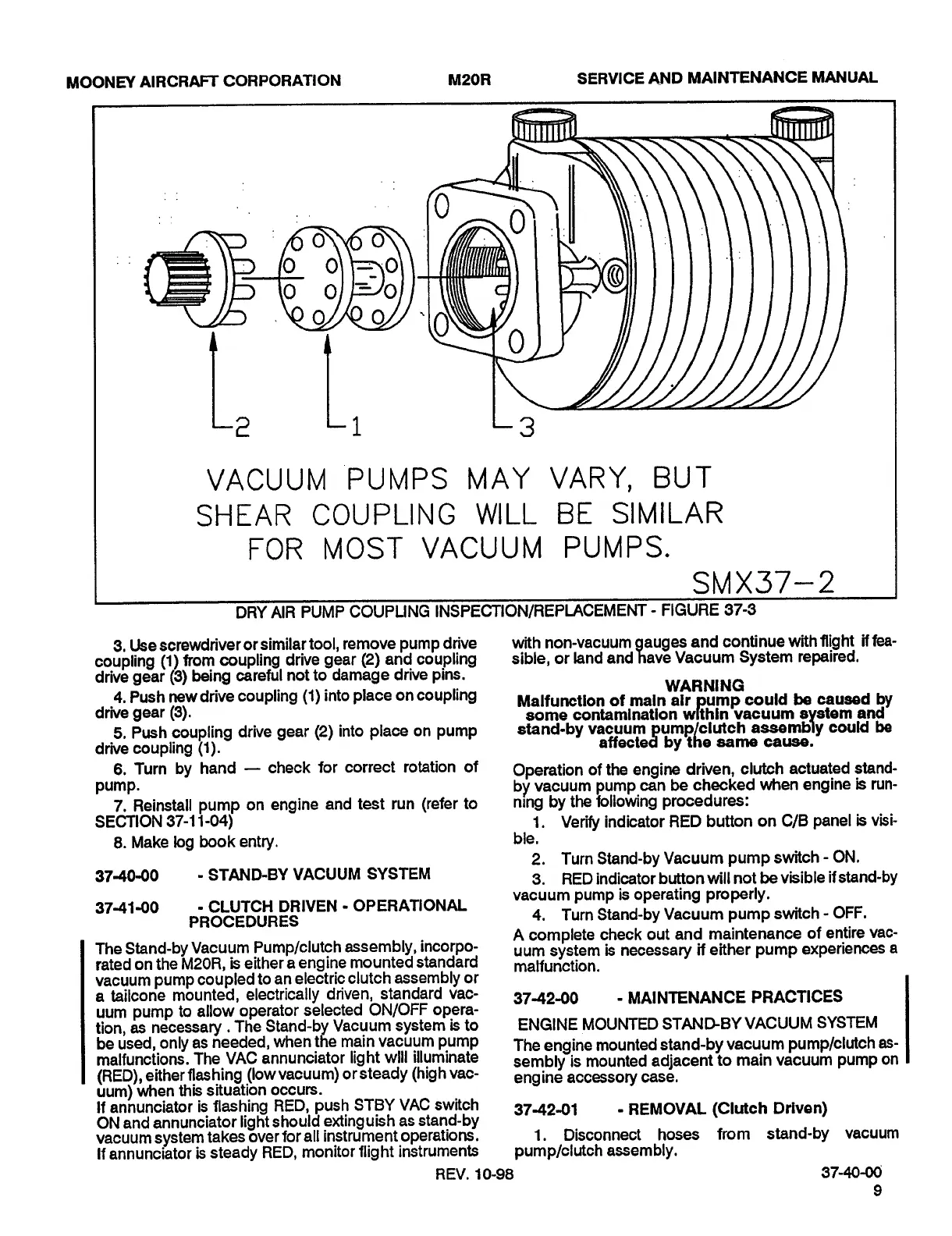
VACUUM
PUMPS
MAY
VARY,
BUT
S~-1EAR
COUP
LING
WILL
BE
SIMILAR
FOR
MOST
VACUUM
PUMPS.
SMX37-2
DRYAIR
PUMP
COUPUNG
INSPECTION/REPLACEMENT
FIGURE
37-5
3,
Use
screwdriver
or
similar
tool,
remove
pump
drive
with
non-vacuum
gauges
and
continue
with
flight
if
fea-
coupling
(1)
from
coupling
drive
gear
(2)
and
coupling
sible,
or
land
and
have
Vacuum
System
repaired.
drive
gear
(3)
being
careful
not
to
damage
drive
pins.
WARNING
4.
Push
new
drive
coupling
(1)
into
place
on
coupling
Malfunction
of
main
air
pump
could
be
caused
by
drive
gear
(3).
some
contamlnation
wlthrn~vacuum
system
and~
5.
Push
coupling
drive
gear
(2)
into
place
on
pump
stand-by
vacuum
pump/clutch
assembly
could
be
drive
coupling
(1).
affected
bylhe
same
cause.
6.
Turn
by
hand
check
for
correct
rotation
of
Operation
of
the
engine
driven,
clutch
actuated
stand-
pump.
by
vacuum
pump
can
be
checked
when
engine
is
run-
7.
Reinstall
pump
on
engine
and
test
run
(refer
to
nlng
by
the
following
procedures:
SECTION
57-11-04)
1.
Verify
indicator
RED
button
on
C/B
panel
is
visi-
8.
Make
log
book
entry,
ble.
2.
Turn
Stand-by
Vacuum
pump
switch
ON.
3740-00
STAND-BY
VACUUM
SYSTEM
3.
RED
indicator
button
will
not
be
visible
if
stand-by
vacuum
pump
is
operating
properly.
37-4140
OPERP~ONAL
4~
TurnStand-hyVacuum
pumpswitch-Off.
A
complete
check
out
and
maintenance
of
entire
vac-
The
Stand-by
Vacuum
Pump/clutch
assembly,
incorpo-
system
is
necessary
if
either
pump
experiences
a
rated
on
the
M20R,
is
either
a
engine
mounted
standard
malfunction.
vacuum
pump
coupled
to
an
electric
clutch
assembly
or
a
tailcone
mounted,
electrically
driven,
standard
vac-
3742-00
MAINTENANCE
PRACTICES
uum
pump
to
allow
operator
selected
ON/OFF
opera-
tion,
as
necessary
.The
Stand-by
Vacuum
system
is
to
ENGINE
MOUNTED
STANDBY
VACUUM
SYSTEM
be
used,
only
as
needed,
when
the
main
vacuum
pump
The
engine
mounted
stand-by
vacuum
pump/clutch
as-
malfunctions.
The
VAC
annunciator
light
will
illuminate
semblyis
mounted
adjacent
to
main
vacuum
pump
on
(RED),
either
flashing
(low
vacuum)
orsteady
thigh
vac-
engine
accessory
case.
uum)
when
this
situation
occurs.
If
annunciator
is
flashing
RED,
push
STBY
VAC
switch
374291
REMOVAL
(Clutch
Driven)
ON
and
annunciator
light
should
extinguish
as
stand-by
vacuum
system
takes
over
for
all
instrument
operations.
1.
Disconnect
hoses
from
stand-by
vacuum
If
annunciator
is
steady
RED,
monitor
flight
instruments
pump/clutch
assembly.
REV.
10-98
37-40-00;
Island Enterprises

Table of Contents