EasyManua.ls Logo

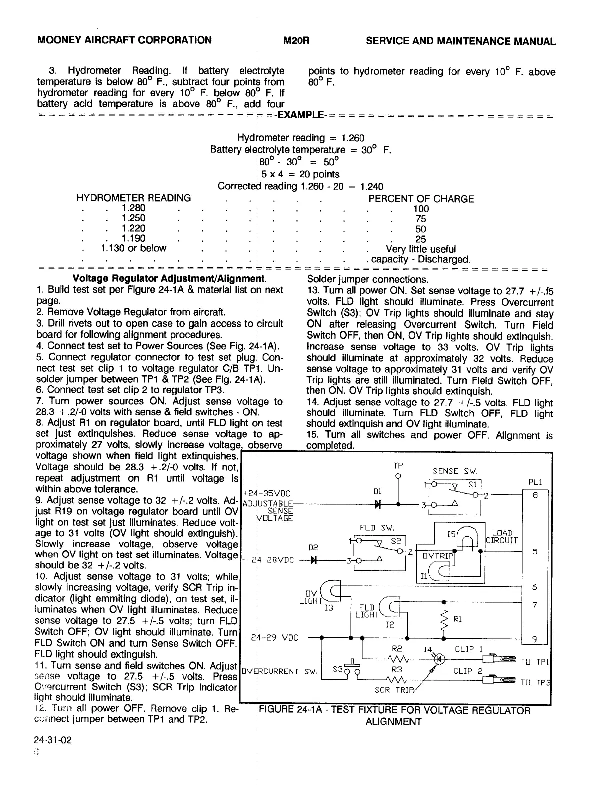
Mooney M20R - Test Fixture for Voltage Regulator Alignment; Voltage Regulator Adjustment;Alignment

Default Icon
360 pages
Print Icon
To Next Page IconTo Next Page
To Previous Page IconTo Previous Page
Loading...
MOONEY
AIRCRAFT
CORPORATION
M20R
SERVICE
AND
MAINTENANCE
MANUAL
3.
Hydrometer
Reading.
If
battery
points
to
hydrometer
reading
for
every
100
F.
above
temperature
is
below
800
F.,
subtract
four
point~
from
800
F.
hydrometer
reading
for
every
100
F.
below
800
F.
If
battery
acid
temperature
is
above
800
F.,
add
four
-EXAMPLE-
Hydrometer
reading
1.260
Battery
elgctrolyte
temperature
300
F.
800
300
500
5
x
4
20
points
Corrected
reading
1.260
20
1.240
HYDROMETER
READING
PERCENT
OF
CHARGE
1.280
100
1.250
75
1.220
50
1.190
_
25
1.130
or
below
Very
little
useful
capacity-
Discharged.
Voltage
Regulator
Adjustm~nt/Alignmeht.
Solder
jumper
connections.
1.
Build
test
set
per
Figure
24-1A
material
list
on
next
13.
Turn
all
power
ON.
Set
sense
voltage
to
27.7
+/-.f5
page,
volts.
FLD
light
should
illuminate.
Press
Overcurrent
2.
Remove
Voltage
Regulator
from
aircraft.
Switch
(S3);
OV
Trip
lights
should
illuminate
and
stay
3.
Drill
rivets
out
to
open
case
to
gain
access
to
!circuit
ON
after
releasing
Overcurrent
Switch.
Turn
Field
board
for
following
alignment
procedures.
Switch
OFF,
then
ON,
OV
Trip
lights
should
extinguish.
4.
Connect
test
set
to
Power
Sources
(See
Fig.
24-1A).
Increase
sense
voltage
to
33
volts.
OV
Trip
lights
5.
Connect
regulator
connector
to
test
set
plugi
Con-
should
illuminate
at
approximately
32
volts.
Reduce
nect
test
set
clip
1
to
voltage
regulator
C/B
TP11.
Un-
sense
voltage
to
approximately
31
volts
and
verify
OV
solder
jumper
between
TP1
TP2
(See
Fig.
24-1A).
Trip
lights
are
still
illuminated.
Turn
Field
Switch
OFF,
6.
Connect
test
set
clip
2
to
regulator
TP3.
then
ON.
OV
Trip
lights
should
extinguish.
7.
Turn
power
sources
ON.
Adjust
sense
voltage
to
14.
Adjust
sense
voltage
to
27.7
+/-.5
volts.
FLD
light
28.3
+.2/-0
volts
with
sense
field
switches
ON.
should
illuminate.
Turn
FLD
Switch
OFF,
FLD
light
8.
Adjust
R1
on
regulator
board,
until
FLD
light
On
test
should
extinguish
and
OV
light
illuminate.
set
just
extinguishes.
Reduce
sense
voltage
to
ap-
15.
Turn
all
switches
and
power
OFF.
Alignment
is
proximately
27
volts,
slowly
increase
voltage
shown
when
field
light
extinguishes.
Voltage
should
be
28.3
+.2/-0
volts.
If
not,l
TP
SENSE
SW.
-I
PL3
repeat
adjustment
on
R1
until
voltage
is
within
above
tolerance.
S11si
+24-35VDC
D1
9.
Adjust
sense
voltage
to
32
+/-.2
volts.
Ad-
ADJUSTA
pd
I
just
R19
on
voltage
regulator
board
until
OV
light
on
test
set
just
illuminates.
Reduce
volt-
VOLTAGE
FLn
sw.
age
to
31
volts
(OV
light
should
extinguish).
rs
LoAn
Slowly
increase
voltage,
observe
voltage
D,
IRCU[T
when
OV
light
on
test
set
illuminates.
Voltagel,
2~-28VDC
U
1
~3-2
OVTRIP
should
be
32
+/-.2
volts.
10.
Adjust
sense
voltage
to
31
volts;
whilel
III
slowly
increasing
voltage,
verify
SCR
Trip
in-
6
ov
dicator
(light
emmiting
diode),
on
test
set,
il-
Lr
luminates
when
OV
light
illuminates.
Faeducel
13
II:GL~I
7
sense
voltage
to
27.5
+1-.5
volts;
turn
FLD
re
R1
Switch
OFF;
OV
light
should
illuminate.
Turn
e4-29
VDC
-t--Ct
--1
9
FLD
Switch
ON
and
turn
Sense
Switch
OFF.
R2
14.
CLIP
1
FLD
light
should
extinguish.
11.
Turn
sense
and
field
switches
ON.
Adjust
OVBRCURRENT
SV
I
S3~
TO
TPL
R3
CLIP
2
r,~nse
voltage
to
27.5
+/-.5
volts.
Press
CT?´•srcurrent
Switch
(53);
SCR
Trip
indicatorl
SCR.TdI
TO
TP
light
should
illuminate.
12.
TLI~YI
all
power
OFF.
Remove
clip
1.
Re-
I
FIGURE
24-1A
TEST
FIXTURE
FOR~VOLTAGE
REGULATOR
ca;lnect
jumper
between
TP1
and
TP2.
ALIGNMENT
24´•-31-02
Island Enterprises

Table of Contents