RS03/06-S/Q Hardware Manual
26
9 / 28 / 2015
+86-400-820-9661
3.4.2 Digital Outputs
3.4.2.1 Y1/ALARM,Y2/IN POSITION,Y3/BRAKE Digital Outputs
The Y1/alarm, Y2/In-position, Y3/brake are optically isolated digital outputs, single-ended, sinking
or souring, max. 30VDC/100mA.
• Y1 can be configured as alarm signal output.
• Y2 can be configured as dynamic in position signal output (dynamic, checking in position all
the time.) It also can be configured as Tach signal output, tach output produce pulses relative
to the motor position with con
figurable resolution. It can also be configured as Timing signal
output, timing output produce 50 pulses relative to one turn of motor revolution.
• Y3 can be configured as signal output to release brake. It can also be configured as static in
position signal output (static, checking in position when motor is stopped).
Y1, Y2 and Y3 can be configured by Step-Servo Quick Tuner as general purpose outputs.
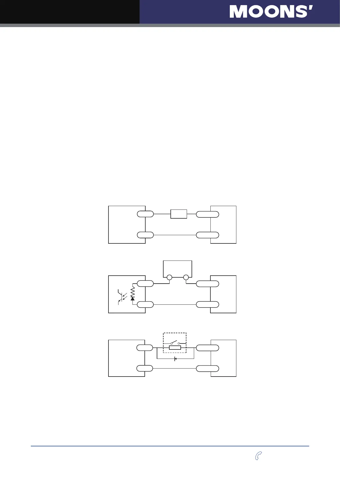
The chats below show how to connect to the output:
NOTE:
Do not connect the outputs to more than 30VDC power supply
.
And the current of each output terminal must not exceed 100mA.
Connecting a Sinking Output
+
-
Load
5 - 24V
Power Supply
RS-S/Q
Connecting a Sourcing Output
COM
IN
PLC
+
-
5 - 24V
Power Supply
RS-S/Q
Driving a Relay
+
-
relay
5 - 24V
Power Supply
1n4935 Suppression Diode
RS-S/Q
Y1/Y2/Y3+
Y1/Y2/Y3 -
Y1/Y2/Y3+
Y1/Y2/Y3 -
Y1/Y2/Y3+
Y1/Y2/Y3 -