17
Rev. 1.0
09/06/2015
MSSTB-R/C Hardware Manual
400-820-9661
3.2 Digital Outputs
3.2.1 Y1, Y2, Y3 Digital Outputs
• Y1 can be used as alarm output or general purpose output.
• Y2 can be used as brake output or general purpose output.
• Y3 cab be used as motion output , tach output, timing signal output(50pulse/rev) or general
purpose output.
Please use STB Congurator software for Y1,Y2 and Y3 function conguration.
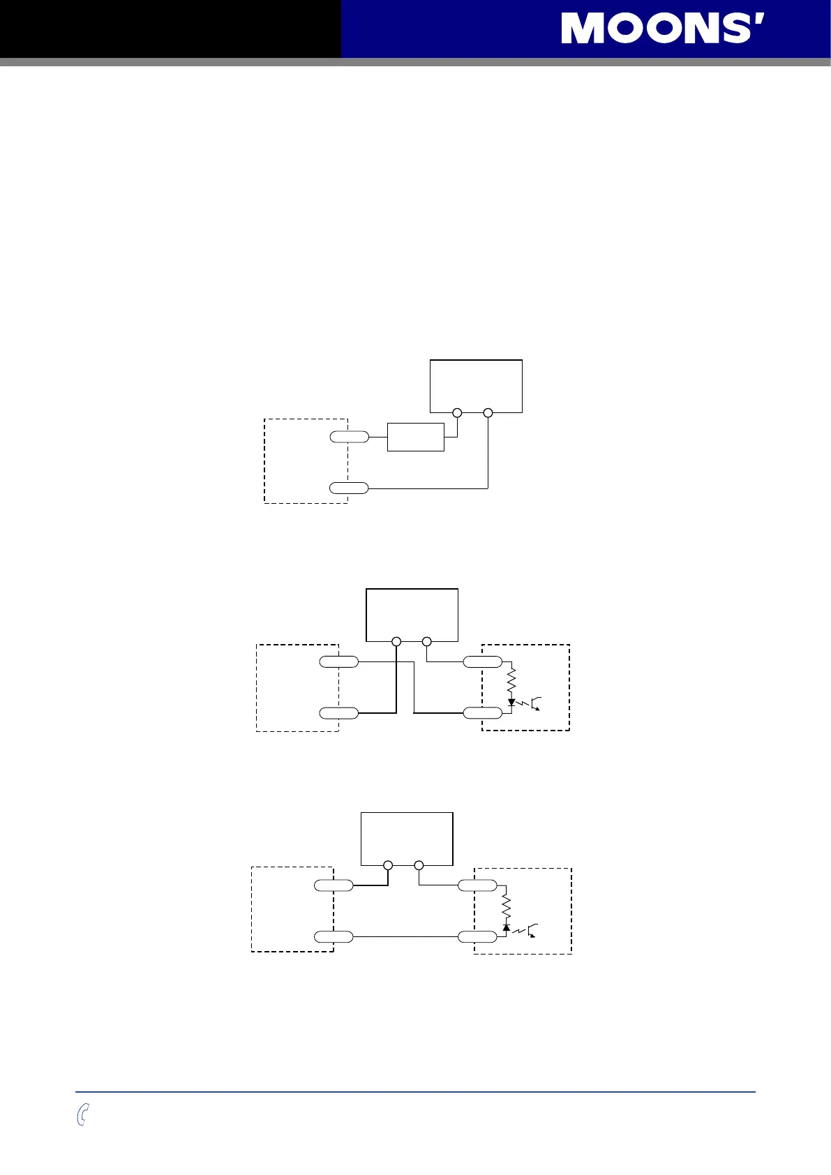
Following graphs shows some common connection methods for the outputs:
NOTE: Do not connect the outputs to more than 30VDC power supply. And the current of
each output terminal must not exceed 100mA.
Connecting a sinking output
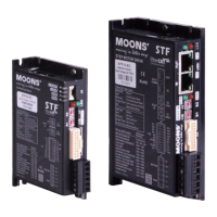
Connecting a sinking output with PLC’s input
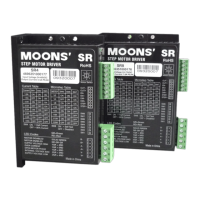
Connecting a sourcing output with PLC’s input
MSSTB
Drive
5-24 VDC
Power Supply
+ –
Load
Y1/2/3-
Y1/2/3+
CLP
CDV 42-5
ylppuS rewoP
+ –
Y1/2/3-
Y1/2/3+
IN
COM
MSSTB
Drive
PLC
5-24 VDC
Power Supply
+
–
Y1/2/3-
Y1/2/3+
COM
IN
MSSTB
Drive
MSSTB
Drive
1N4935 suppression diode
5-24 VDC
Power Supply
+ –
relay
Y1/2/3-
Y1/2/3+