www.miinet.comMoore Industries-International, Inc.
- 61 -
User’s Manual
224-790-00K
May 2018
Programmable Limit Alarm Trips
SPA
2
SECTION 5
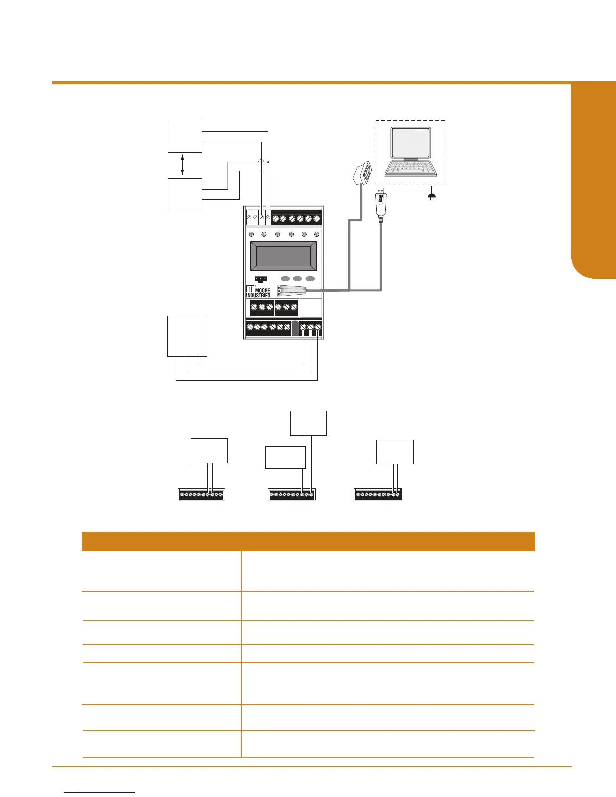
Figure 5.2. SPA
2
TPRG Hook-Up Diagram For PC Configuration
Table 5.1. Necessary Equipment to Configure the SPA
2
HLPRG - Current or
Voltage Source
TPRG - Variable Input Simulator
for Thermocouple, RTD, Millivolt,
Potentiometer, or Decade Resistance
Box
Accurate to 0.05% of span for the intended application
Accurate to 0.05% of span for the intended application
Microsoft Windows based PC;
16Mb free RAM; 20MB free disk space on hard drive
Microsoft Windows XP, 7, or 10
1 (one) serial port or one available USB port
Version 1.0 or greater, successfully installed to the hard drive
Moore Industries PC
Configuration Software
Personal Computer
Power Supply
Multimeter (optional)
Universal, 21.6-125Vdc/90-260Vac
Accurate to ±0.009% of span; e.g., HP Model 3478A
Communication Cable or
USB Cable)
Part# Communications Cable 803-053-26A, USB Cable Part# 804-030-26, or
Fuse Protected USB Cable 804-030-26A
Device Specifications
+
–
+
–
EXTERNAL
POWER
SUPPLY
+
–
MULTIMETER
OR
DCS
MULTIMETER
OR
DCS
+
–
MULTIMETER
OR
DCS
HOOK-UPS FOR OUTPUT TRIMMING
PC
AC OR DC
POWER
SUPPLY
GND
SPA
READY
INPUT TRIP 1 TRIP 2
TRIP 3 TRIP 4
SELECT
DOWN
UP
COM
2
SITE
PROGRAMMABLE
ALARM
MILLIVOLT
SOURCE
OR T/C
SIMULATOR
_
+
OHMS
OR RTD
SIMULATOR
TO SERIAL
(COM) PORT
OF PC
To USB
(COM)
Port of PC
+
-