www.miinet.comMoore Industries-International, Inc.
- 63 -
User’s Manual
224-790-00K
May 2018
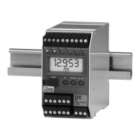
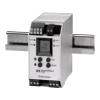
Programmable Limit Alarm Trips
SPA
2
SECTION 5
7. Communications– Notifies user of current PC connection/communications status.
8. Input Tab– Use this tab to set your input parameters. Refer to the Input section for a complete
description.
9. Display Tab– Used to set up the appearance of the SPA
2
LCD screen. Refer to the Display
section for a complete description.
10. Alarms Tab (1 & 2 and 3 & 4)– Alarm parameters are configured using these windows. Alarms
1 & 2 are located in the same window. Alarms 3 & 4 are grouped together in another window. Refer
to the Alarms section for a complete description.
11. Analog Output Tab– Configuration of the analog output (if your instrument is equipped with the
-AO option) is performed here. Refer to the Analog Output section for a complete description.
12. Scaling Tab– If you choose to enable the scaling feature, the parameter would be configured at
this window. Refer to the Scaling section for a complete description.
13. Custom Curve Tab– The SPA
2
has two modes of operation: linear mode and custom mode.
In linear mode, the scaled output is proportional to the scaled input. In custom mode, reached by
selecting the Custom Curve tab, you define a special linearization function. Refer to the Custom
Curve section for a complete description.
Note: The Custom Curve parameter can ONLY be configured using your PC and PC Configuration
Software Program. It cannot be configured using he front panel push buttons.
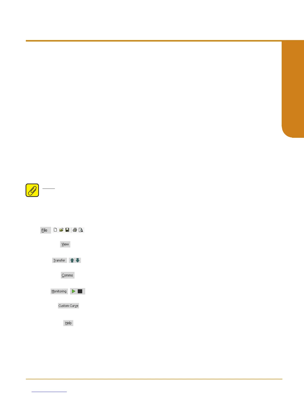
Status and Tool Bar Legend
Allows such functions as New,
Open, Save and Print
Allows you to Upload and
Download configurations
Select the PC Port
(Com Port) that you will use
Allows you to Monitor and
Stop monitoring processes
Provides functions specific to
your Custom Curve table
Controls whether Tool and Status
Bars are viewed on the screen
Displays the version of the SPA IS
Configuration Program
2