6881076C20-E February 3, 2003
Radio Alignment Procedure: ASTRO Digital Spectra and Digital Spectra Plus Tuner Software 6-15
- Attenuation: 20dB
- Mon RF in: RF I/O
- Meter: RF Display
- Mode: STD
- Input Level: uV or W
- Display: Bar Graphs
- Squelch: Mid-range or adjust as necessary
• Initial set up using the 8901_ Series Modulation Analyzer:
- Press the green Automatic Operation button on the analyzer.
- Press the FREQ key.
- Type 7.1 followed by SPCL button to set the 8901_ modulation analyzer for maximum
accuracy.
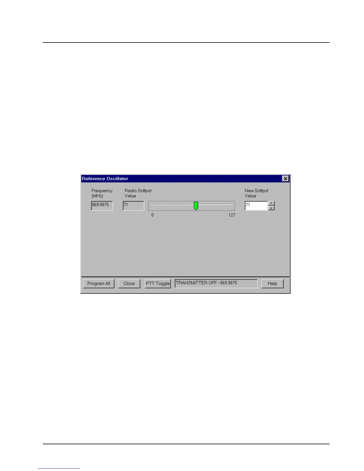
1. Select the Reference Oscillator alignment screen. See
Figure 6-13.
Figure 6-13. Reference Oscillator Alignment Screen
2. If you are using the R-2670 analyzer, enter the frequency displayed on the RSS screen in the
“RF control” section of the R-2670. Under the “Meter” section of the display, choose RF
DISPLAY.
3. Left-click the PTT Toggle button on the screen to make the radio transmit. The screen
indicates whether the radio is transmitting.
4. Wait five seconds until the analyzer reading stabilizes, and then record the transmitter
frequency.
5. Adjust the reference oscillator’s softpot value until the measured value is as close as possible
to the frequency shown on the screen. Allow approximately five seconds for the analyzer
frequency reading to stabilize after each change. See
Table 6-1 on page 6-4 and Table 6-3 on
page 6-16
.

 Loading...


