February 3, 2003 6881076C20-E
9-12 Basic Troubleshooting: Synthesizer Troubleshooting
NOTE:The P501 pins can be probed on the extender cable (see the P501 Extender Cable
diagram on
page 10-6).
9.7 Synthesizer Troubleshooting
The following table can help you troubleshoot problems that might occur in the synthesizer section of
your radio.
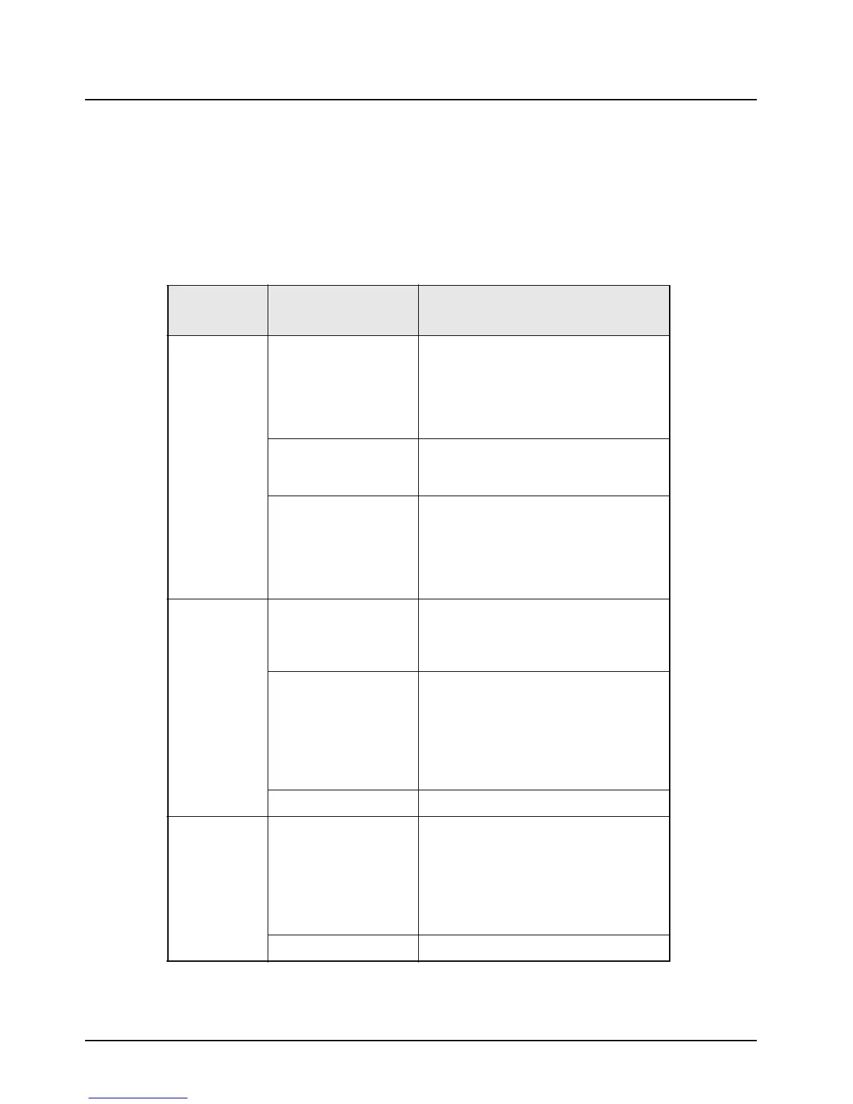
Table 9-7. Synthesizer Troubleshooting Chart
Symptom Possible Cause
Correction or Test (Measurements
Taken at Room Temperature)
Does Not Lock
on Any
Channel
VCO With radio in receive mode, measure pin 1
of J601 using a high impedance probe.
Measured level should be -5 dBm ±6 dB,
and the frequency should be 370 to
380MHz.
If not, replace the VCO board.
Reference Oscillator/RF
Board
Is there >1.5 Vp-p of 2.1 MHz on pin 21 of
J500?
If not, replace the RF board.
VOCON Board Do both the chip select lines (pins 16 & 20
of J500) go low during mode changes?
Is there data on the clock & data lines
going into the RF board (pins 18 & 19 of
J500)?
If not, replace the VOCON board.
Does Not Lock
on Some
Channels
Programming Check the mode programming information
to ensure that the correct frequency
programming information has been
entered.
VCO With the radio in receive mode; unplug the
loop feedback coax from the VCO board
to the RF board.
Measured level should be -5 dBm ±5 dB,
and the frequency should be 370 to 380
MHz.
If not, replace the VCO board.
RF Board Replace the RF board.
Does Not Lock
in Tx (or
Talkaround
RF Board Check the Aux bit states (pin 9 & 11 J601).
When changing from receive to transmit to
talkaround, pin 9 and 11 of J601 should
alternate between a high voltage (>8V)
and a low voltage (<1V).
If either pin does not alternate between
these voltages, replace the RF board.
VCO Replace the VCO board.

 Loading...


