DCS 1800 StarTAC PERSONAL CELLULAR TELEPHONE
68P09304A85 BDesc2
2 19/07/97
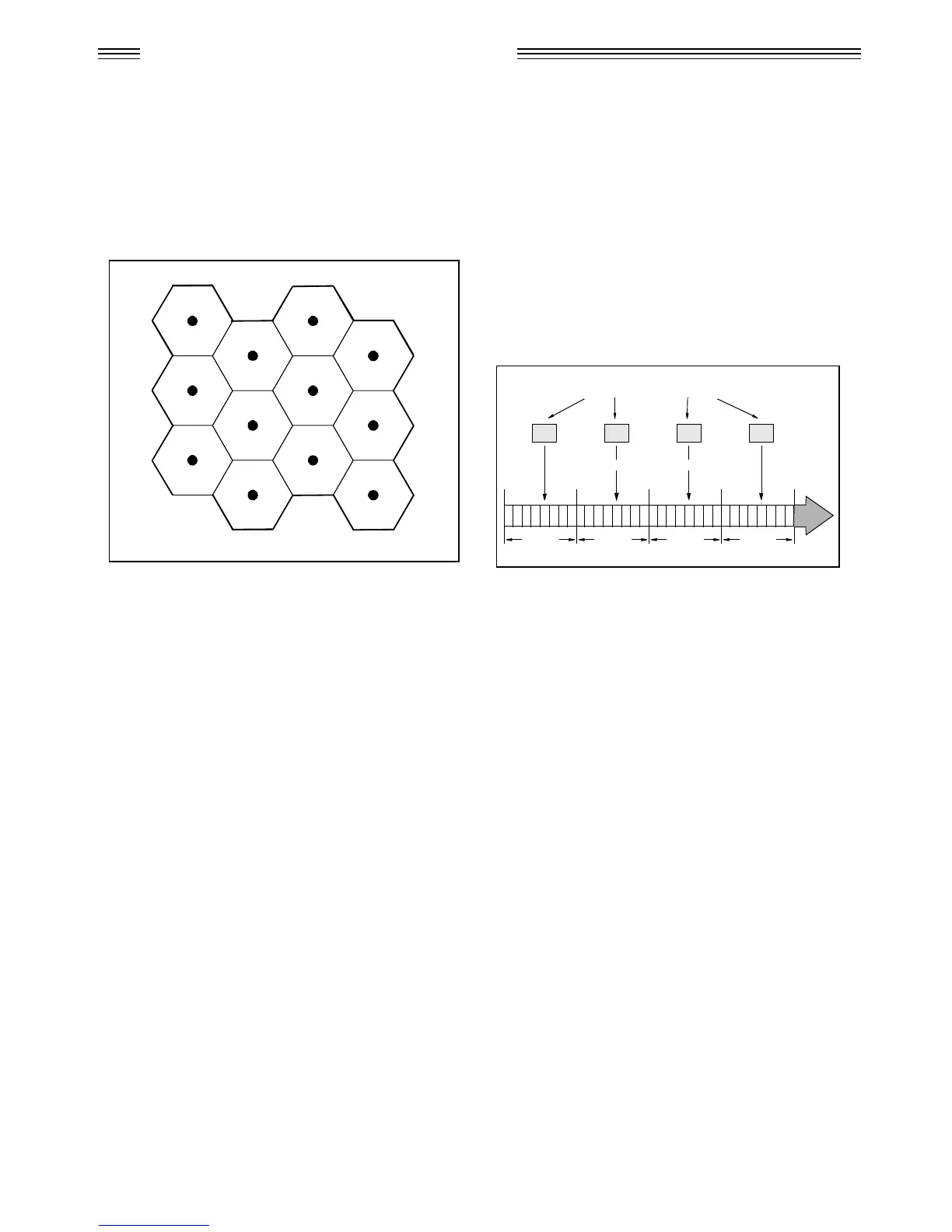
Refer to Figure 1. In the figure, the area bounded by bold
lines represents the total coverage area of a hypothetical
system. This area is divided into several cells, each
containing a cell site (base station) operating on a given set
of channels which interfaces radiotelephone subscribers to
the telephone switching system.
The radiotelephones themselves are capable of operation on
any channel in the system, allowing them to operate in any
cell. Due to the low power requirements for communications
between radiotelephones in a particular cell and the cell site,
operating channels may be repeated in cells which are outside
the coverage area of each other.
For example, presume that cell A operates on channels
arbitrarily numbered 1 through 8, cell B operates on channels
9 through 16, cell C operates on channels 17 through 24 and
cell D operates on channels 1 through 8 (repeating the usage
of those channels used by cell A). In this system, subscribers
in cell A and subscribers in cell D could simultaneously
operate on channels 1 through 8. The implementation of
frequency re-use increases the call handling capability of the
system, without increasing the number of available channels.
When re-using identical frequencies in a small area, co-
channel interference can be a problem. The D.C.S. system
can tolerate higher levels of co-channel interference than
analogue systems, by incorporating digital modulation,
forward error correction and equalization. This means that
cells using identical frequencies can be physically closer,
than similar cells in analogue systems. Therefore the
advantage of frequency re-use can be further enhanced in a
D.C.S. system, allowing greater traffic handling in high use
areas.
By incorporating Time Division Multiple Access (TDMA)
several calls can share the same carrier. The carrier is divided
into a continuous stream of TDMA frames, each frame is
split into eight time slots. When a connection is required the
system allocates the subscriber a dedicated time slot within
each TDMA frame. User data (speech/data) for transmission
is digitized and sectioned into blocks. The user data blocks
are sent as information bursts in the allocated time slot of
each TDMA frame, see Figure 2. The data blocks are
modulated onto the carrier using Gaussian Minimum Shift
Keying (GMSK), a very efficient method of phase
modulation.
Each time an information burst is transmitted, it may be
transmitted on a different frequency. This process is known
as frequency hopping. Frequency hopping reduces the effects
of fading, and enhances the security and confidentiality of
the link. A D.C.S. radiotelephone is only required to transmit
for one burst in each frame, and not continually, thus enabling
the unit to be more power efficient.
Each radiotelephone must be able to move from one cell to
another, with minimal inconvenience to the user. The mobile
itself carries out signal strength measurements on adjacent
cells, and the quality of the traffic channel is measured by
both the mobile and the base station. The handover criteria
can thus be much more accurately determined, and the
handover made before the channel quality deteriorates to the
point that the subscriber notices.
When a radiotelephone is well within a cell, the signal
strength measured will be high. As the radiotelephone moves
towards the edge of the cell, the signal strength and quality
measurement decreases. Signal information provides an
indication of the subscriber’s distance from the base station.
As the radiotelephone moves from cell to cell, its control is
handed from one base station to another in the new cell. This
change is handled by the radiotelephone and base stations,
and is completely transparent to the user.
01234
5
67012 34
5
6701234
5
6701234
5
67
FRAME 0 FRAME 3FRAME 2FRAME 1
USER DATA SECTIONED INTO BLOCKS
INFORMATION BURSTS SENT IN ALLOCATED TIME SLOTS
Figure 1. Hypothetical Cell System Figure 2. Time Division Multiple Access Transmission
 Loading...