Customer Services Publishing
Easter Inch, Bathgate, West Lothian
EH 48 2 EH, United Kingdom
GDis7
© Motorola Ltd. 1997
All Rights Reserved
Printed in U.K.
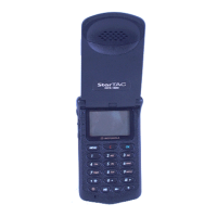
DCS 1800 StarTAC PERSONAL
CELLULAR TELEPHONE
DISASSEMBLY
68P09304A85
19/07/97
25
Cellular Subscriber Group
DISASSEMBLY INSTRUCTIONS
1. INTRODUCTION
The DCS 1800 StarTAC cellular telephone is assembled
using a simple slide and press fit between front and back
housings followed by positioning of two fixing screws. The
antenna does not have to be removed before disassembly is
started, the antenna can be removed when the back panel is
free. Reasonable care should be taken during the disassembly
and reassembly of the unit in order to avoid damaging or
stressing the housing and internal components. Ensure that a
properly grounded high impedance conductive wrist strap is
used while performing these procedures on electronic units.
2. RECOMMENDED TOOLS
The following tools are recommended for use during the
assembly/disassembly of the personal telephone.
• Anti-Static Mat Kit 0180386A82; includes:
— Anti-Static Mat 66-80387A95
— Ground Cord 66-80334B36
— Wrist Band 42-80385A59
• Plastic Bladed Tool (SLN7223A
Many of the integrated circuit devices used in this
equipment are vulnerable to damage from static
charges. Ensure that adequate static protection is
in place when handling, shipping, and servicing
CAUTION
•Τ6 Torx Screw Driver
• Antenna Removal Tool (SYN5179)
• A small flat bladed screw driver,
3. DISASSEMBLY PROCEDURE
3.1 DISASSEMBLY PROCEDURE
The following information describes the procedure for
removing and accessing various parts of the DCS1800
StarTAC.
4. ASSEMBLY PROCEDURE
Once the unit is disassembled and the repair is carried out it
then becomes obvious that to assemble the unit, the
procedure is the reverse of that previously completed for
disassembly. Note that the housings must be securely held
together and the screws torqued appropriately for assembly.
Failure to secure the housings properly could result in
possible damage.
Refer to the mechanical exploded view on
page 38, as necessary, while performing the
disassembly/assembly procedures.
NOTE

 Loading...