Customer Services Publishing
Easter Inch, Bathgate, West Lothian
EH48 2EH, United Kingdom
ETrbl5
© Motorola Ltd. 1997All
Rights Reserved
Printed in U.K.
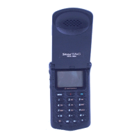
DCS 1800 StarTAC PERSONAL
CELLULAR TELEPHONE
TROUBLESHOOTING
ASSEMBLY REPLACEMENT LEVEL
68P09304A85
19/07/97
17
Cellular Subscriber Group
TROUBLESHOOTING
1. INTRODUCTION
Assembly replacement level troubleshooting and repair of
the DCS 1800 StarTAC personal telephone is limited to
isolation and replacement of the following main items only:-
• Antenna
• Battery
• Logic/RF Assembly
• Keypad/Display Board
• Front/Rear Housings
• Keypad Membrane
• Flip Assembly
It is recommended that known good replacement parts and
assemblies be available to be used for troubleshooting by
substitution, and for replacement of parts/assemblies found
to be defective.
If at any time the unit is disassembled, whether repaired or
not, it is recommended that a simple test of making a call and
checking signal strength and transmit and receive audio
quality is carried out. Appropriate action should then be taken
on the outcome of the test.
2. TROUBLESHOOTING AND REPAIR
The troubleshooting information in Table 1 shows some
typical malfunction symptoms and the corresponding
verification and repair procedures. Refer to the disassembly
instructions located in the disassembly section of this manual
for instructions on removing and replacing parts/assemblies
from the personal telephone. If the Logic/RF assembly is
replaced a personality transfer will be necessary, see page 23
for more information.
3. TESTING AFTER REPAIR
After any repair work has been carried out, the unit should
be thoroughly tested to ensure that its operates correctly. This
is especially important if the Logic/RF assembly is replaced.
For general repairs which do not include replacing the Logic/
RF assembly, simply placing a call and checking signal
strength, and transmit and receive audio quality is normally
sufficient.
When the Logic/RF assembly is replaced, the unit must have
a comprehensive test on a DCScompatible communications
analyser. See ‘Testing Procedure’ on page 16 for further
details. The simple test of placing a call on air is usually
carried out on completion of this Test to finalise the testing
procedure.
Additionally, a further audio test “Buzz Test” should be
carried out to eliminate the possibility of transmitter
interference to the audio path. Refer to table A.
Table A
Command Function
08# Unmute RX audio Path
10# Unmute TX audio path
36# Initiate Acoustic Loopback
434# Change audio Path
477
# Set volume level to 7 max
11700#
Set LO to CH700
1200# Set power level to max
310# Initiate PRS (Starts TX)
01# To terminate test
If any distortion or buzzing is heard through the earpiece after
entering the above sequence, refer to the DISASSEMBLY
instructions in this manual and ensure that the earpiece and
microphone are seated correctly and that there is no visible
damage to the display PCB/front housing connector. If no
fault found and symptoms persist replace Logic/RF board
(Table 1, symptom 1c).
Defective Logic/RF assemblies must be replaced
with pre-tested, pre-phased assemblies.
NOTE

 Loading...