CAR KITS
JMCK10 68P09304A85-O
19/07/97
57
2.6 CABLE ROUTING
If the vehicle is provided with wire troughs in the door sills,
use them to provide maximum protection for the cables and
to simplify cable installation routing. In vehicles without
cable troughs, route the cables in such a manner as to protect
them from pinching, sharp edges and crushing.
As an alternative, route any cables along the transmission
hump under the carpeting. Always use rubber grommets
when a cable must pass through a metal panel hole.
Regardless of the routing method used, try to ensure that all
in line connectors and fuses are accessible.
2.7 POSSIBLE INTERFERENCE WITH ANTI-
LOCK BRAKING SYSTEMS
Performance of electronically controlled brake and/or
guidance systems can, under certain conditions, be subject
to interference by radio telephone operation. Although the
radio meets or exceeds all rf emission requirements, the rf
power emitted from the antenna cannot be eliminated
without seriously affecting the radio’s operation. All
automotive control systems have to meet stringent EMI
specifications, but a defective control system may go
undetected until it becomes necessary to operate in the
proximity of a transmitting antenna.
Therefore, electronically controlled brake and/or guidance
systems should be checked very carefully and at different
speeds for any sign of abnormal operation. See Section 4 for
further information on performance verification.
With the aid of the vehicle service manual, locate the
braking modulator and observe the following points:-
• Mount the transceiver as far as possible from the
braking modular box.
• Mount the external antenna on the opposite side of the
vehicle, to that which the braking modular box is
located.
• Route all cables on the opposite side of the vehicle
from the braking modulator box.
• See section 4.2 on page 61 of this manual for
additional ABS tests.
IMPORTANT
In vehicles equipped with electronically
controlled anti-lock braking systems, route all
cables on the opposite side of the vehicle from
the braking modular box. This will reduce any
possible interference from the car kit. See
3. INSTALLATION
Refer to page 55,Figure 2. (connections diagram) when
working through the following installation sections.
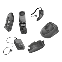
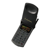
3.1 MOUNTING THE SMART HANDSET CRADLE
Step 1. Select a mounting surface capable of supporting
the weight of the assembly. Be sure to allow
enough clearance for easy and unobstructed
insertion/removal, of the handset to/from the
cradle. Also ensure that the handset display is
clearly visible from a comfortable position.
Step 2. Using the mounting bracket as a template, mark
four holes at the desired mounting location. Using
an awl or similar device, open the holes at the
marked positions.
Step 3. Using a 3.2mm bit, drill the four mounting holes
and mount the bracket to the vehicle using the
four self tapping screws provided. Attach the
hang-up cup on to the cradle and adjust to the
required angle, before tightening the angle
screws.
3.2 DHFA (ADAPTER BOX) INSTALLATION
The DHFA has a mounting plate that will allow for secure
mounting in the desired location. Refer to Figure 1 for cable
connections. Install the adapter box as follows
Step1. Temporarily position the DHFA to verify the
desired mounting location, checking for clearance
and accessibility for cable connection.
Using the surface as a template, mark four holes in
the selected location.
Step 2. Using an awl or similar device, open the holes at
the marked locations. This should be done before
drilling to avoid damage to the mounting surface.
Step 3. Drill the four mounting holes and secure the
DHFA to the surface using the four screws
provided.
CAUTION
Exercise extreme care in order to avoid drilling
into the fuel tank, or another vital part of the
vehicle.
 Loading...