TROUBLESHOOTING
ETrbl5 68P09304A85
19/07/97 21
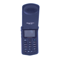
Table 1. DCS 1800 StarTAC Cellular Telephone Troubleshooting and Repair Chart (Assembly Replacement Level).
SYMPTOM PROBABLE CAUSE VERIFICATION AND REMEDY
7. Personal telephone will not
recognize/accept SIM card
a) SIM card defective Initially check that the contacts on the card are not dirty; clean if necessary,
and check if fault has been eliminated. If the contacts are clean, insert a
known good SIM card into the portable telephone. Power up the unit and
confirm whether or not the card has been accepted. If the fault no longer
exists, the defective SIM card should be replaced. If the SIM card is not
at fault, proceed to b.
b) SIM card not being read. Ensure that the SIM card is pushed fully home into it’s recess. If all ok,
proceed to c.
c) Logic/RF Board Assembly
defective.
Replace Logic/RF Board Assembly (refer to symptom 1c). Verify that the
fault has been cleared and re-assemble the unit with the new PCB.
8. Phone does not sense when flip is
opened or closed (usually indicated by
inability to answer incoming calls by
opening the flip, or inability to make
outgoing calls).
a) Magnet in flip defective. Replace flip assembly with known good one (refer to the DISASSEMBLY
instructions in this manual. Place call to portable phone and verify ability
to answer by opening flip. If fault still present, replace original flip
assembly and proceed to b.
b) Reed switch defective. Gain access to Keypad/Display board as described in the DISASSEMBLY
instructions in this manual. Unsolder the reed switch and replace with a
known good one. Reassemble unit. Place call to portable phone and verify
ability to answer by opening flip. If fault still present, replace original reed
switch and proceed to c.
c) Keypad/Display board is
defective.
Replace the Keypad/Display board with a known good one. Place call to
portable phone and verify that the fault has been eliminated. If not at fault,
proceed to d.
d) Logic/RF Board Assembly
defective.
Replace Logic/RF Board Assembly (refer to symptom 1c). Verify that the
fault has been cleared and re-assemble the unit with the new PCB.
9. Vibrator feature not functioning. a) Vibrator motor defective. Replace vibrator motor. If fault still present, replace original vibrator
motor and proceed to b.
b) Logic/RF Board Assembly
defective.
Replace Logic/RF Board Assembly (refer to symptom 1c). Verify that the
fault has been cleared and re-assemble the unit with the new PCB.
10. Internal Charger not working. c) Faulty charger circuit on main
board.
Test a selection of batteries in the rear pocket of the desktop charger. Check
LED display for the charging indications. If these are charging ok, then
the internal charger is at fault. Replace main PCB.
11. Real Time Clock resetting when
standard battery is removed.
Lithium button cell in the Flip may
be depleted.
Replace Flip to check. If ok, replace original Flip and replace button
battery.

 Loading...