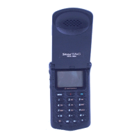
DCS 1800 StarTAC CELLULAR TELEPHONE
68P09304A85 ETrbl5
20 19/07/97
Table 1. DCS 1800 StarTAC Cellular Telephone Troubleshooting and Repair Chart (Assembly Replacement Level).
SYMPTOM PROBABLE CAUSE VERIFICATION AND REMEDY
4. Incoming call alert transducer audio
distorted or volume is too low.
a) Connections to/from Keypad/
Display circuit board faulty.
Gain access to Keypad/Display board as described in the DISASSEMBLY
instructions in this manual. Check connection to alert transducer. If
connection is not at fault, proceed to b.
b) Alert transducer defective. Gain access to alert speaker (located on the Keypad/Display board) as
described in the DISASSEMBLY instructions in this manual. Unsolder
the alert speaker and solder on a known good alert speaker. Place call to
personal telephone from landline or other mobile/personal telephone and
verify alert signal volume and clarity. If good, re-assemble portable with
new alert speaker. If alert speaker not at fault, re-install original alert
speaker and proceed to c.
c) Logic/RF Board Assembly
defective.
Replace Logic/RF Board Assembly (refer to symptom 1c). Verify that the
fault has been cleared and re-assemble the unit with the new PCB.
5. Personal telephone transmit audio
is weak, (usually indicated by called
parties complaining of difficulty in
hearing voice from personal phone).
a) Microphone connections to
Keypad/Display board defective.
Gain access to the Microphone as described in the DISASSEMBLY
instructions in this manual. Check connections and if OK, proceed to b.
b) Microphone defective. Gain access to microphone (located on keypad membrane). Disconnect
and substitute a known good Microphone. Place a call and verify
improvement in portable transmit signal as heard by called party. If good,
re-assemble portable with new Microphone. If Microphone is not at fault,
re-install original Microphone and proceed to c.
c) Logic/RF Board Assembly
defective.
Replace Logic/RF Board Assembly (refer to symptom 1c). Verify that the
fault has been cleared and re-assemble the unit with the new PCB.
6. Personal telephone receive audio is
weak and/or distorted.
a) Connections to/from Logic/RF
circuit board defective.
Gain access to Logic/RF board as described in the DISASSEMBLY
instructions in this manual. Check connection and the flexistrip from the
earpiece to the Logic/RF circuit board. If connection is not at fault,
proceed to b.
b) Earpiece Speaker defective. Gain access to the earpiece speaker as described in the DISASSEMBLY
instructions in this manual. Substitute a known good earpiece speaker.
Place a call and verify improvement in earpiece audio. If better,
reassemble the phone with the good earpiece speaker. If it was no better
then re-install the original component and proceed to c.
c) Antenna assembly is defective. Attempt a re-phasing of the unit and recheck symptom. If symptom the
same but unit re-phases correctly, check to make sure the two antenna
connectors are soldered to the main board correctly and that the antenne
is making good contact with them. If ok, substitute a known good antenna
assembly. If this does not cure the fault , re-install the original assembly
then proceed to d.
d) Logic/RF Board Assembly
defective.
Replace Logic/RF Board Assembly (refer to symptom 1c). Verify that the
fault has been cleared and re-assemble the unit with the new PCB.

 Loading...