DCS 1800 starTAC CELLULAR TELEPHONE
68P09304A85-O JMCK10
58 19/07/97
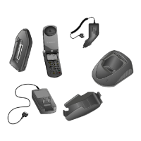
3.3 StarTAC CRADLE INSTALLATION
The adjustable angle mounting bracket included with this
kit provides a convenient means for mounting the cradle. In
a typical application the hang up cup mounts directly to the
bracket using the machined screws provided. Install the
bracket as follows
Step 1. Loosen the two angle adjusting screws on each
side of the bracket and remove the bracket base
from the surface base.
Step 2. Using the screws provided, attach the mounting
bracket to the bottom of the cradle.
Step 3. Temporarily position the bracket to verify the
desired mounting location. Check for clearance
and operating convenience. Using the surface as a
guide, mark four holes on the selected location.
Step 4. Using an awl or similar device, open the four
marked holes. This should be done prior to drilling
to avoid damage to the mounting surface.
Step 5. Drill the four holes and secure the DHFA to the
surface using the screws provided.
Step 6. Mount the base to the surface base at the desired
angle and securely tighten the angle adjusting
screws.
NOTE: Please ensure that the starTAC Cellular phone
connector attached to the cable is fully inserted
into the adapter box.
3.4 ELECTRICAL CONNECTIONS
The best power connection point for the positive primary
power wire (red), is at the positive terminal of the battery.
Often direct connection to the battery terminal is
inconvenient, and it may be necessary to connect the
positive lead to the vehicle’s fuse block. The negative power
wire (black) must be taken to a good vehicle chassis ground,
or the negative terminal of the battery.
Step 1. Route the power cables to the desired points of
termination.
Step 2. Cut the red wire to position the supplied F1, 4A
fuse holder in an easily accessible position. Then
route the cable to a constant positive supply.
Ensure that any wires routed through holes in the
vehicles body are protected by a suitable
grommet.
Step 3. If the fused red wire is to be connected directly to
the positive battery terminal, strip the end of the
wire, and crimp on the larger of the two supplied
ring lugs. Then connect to the positive battery
terminal.
Step 4. The joining of two wires should be achieved using
an in-line crimp connector (supplied).
Step 5. Cut the green wire to position the supplied F2 3A
fuse holder in an easily accessible position. Then
route the cable to an ignition switch controlled
positive supply. The point of connection should:-
• Go to +12V with the ignition switch on.
• Go low while the starter is engaged.
• Returns to +12v with the engine running.
Connection between the green wire and an ignition
controlled vehicle wire should take place via a splice
connector (supplied), without stripping the wire.
Step 6. Strip the other end of the fused green wire and the
end of the green wire from the power cable. Join
the two wires using a supplied in-line crimp
connector.
Step 7. Crimp the remaining ring lug to the black ground
wire, after stripping the end, and bolt to the
vehicle frame. Strip the other end of the black
wire, and the end of the ground wire from the
regulator. Join the two wires using a supplied in-
line crimp connector.
Step 8. Check the power cable positive connection and
verify that it is the correct polarity. Carefully
inspect all cables and connections. Insert the 4A
fuse into fuse holder F1 on the red lead, and the
3A fuse into fuse holder F2 on the green lead.
3.5 ENTERTAINMENT MUTE/AUX ALERT
IMPORTANT
The negative power wire must be fused if it is
connected directly to the negative terminal of
IMPORTANT
If the ignition sense wire is not installed as
indicated, the vehicle battery may be discharged
during periods when the engine is not running,
and the convenience on/off feature will be

 Loading...