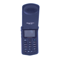
DCS 1800 starTAC CELLULAR TELEPHONE
68P09304A85-O JMCK10
60 19/07/97
Step 5. Push the collar onto the plug assembly, and then
slide the ferrule over the braid until the flange
butts against the connector body.
Step 6. Crimp the ferrule, preferably at both ends, using
the crimping tool.
Step 7. Trim the centre conductor flush with the end of
the centre contact.
Step 8. Install and route the antenna coaxial cable to the
d470DBR
AID
CONNECTOR
BODY
COLLAR
FERRULE
CRIMP CENTRE
CONTACT AFTER
INSERTING CABLE
PROTRUDING CENTRE
CABLE INSERTED
INTO CONNECTOR
COLLAR PUSHED
OVER CONNECTOR
BODY
PUSH FERRULE FORWARD
OVER BRAID. FLANGE
BUTTS AGAINST
CONNECTOR BODY.
CRIMP FERRULE TO
Figure 5. Antenna connector Assembly Detail.
chosen antenna location, and follow the
installation instructions given with the specific
antenna.
Step 9. Confirm that the coaxial cable can be easily
connected to the car kit.
Step 10. Check the performance of the antenna installation
(see section 4), before connecting the antenna
installation up to the kit.
4. PERFORMANCE CHECKS
4.1 CHECKING ANTENNA PERFORMANCE
Once a car kit has been installed, the performance of the
antenna installation must be checked. This is normally
achieved by commanding the radiotelephone to transmit a
signal, and then measure any reflected power. However due
to the pulsed power characteristics of any digital radio,
reflected pulsed power can only be measured using a
specially designed VSWR (Voltage Standing Wave Ratio)
meter.
If you do not have access to such an item, then a VSWR
meter with a built in rf generator may be used to test the
antenna and cable. The internal rf generator must be capable
of producing a 1800MHz signal.
The procedure for testing is as follows:-
Step 1. Connect the VSWR meter to the installation, see
VSWR user guide for further details, and key up
the transmitter/rf generator.
Step 2. Measure the forward power (Pf) and the reverse
power (Pr). Calculate the VSWR using the
following equation.
7mm
24mm
15mm
Figure 6. Coaxial Cable Stripping Detail.

 Loading...