5.5
Connectors and Pin Assignment of Ethernet Expansion Head
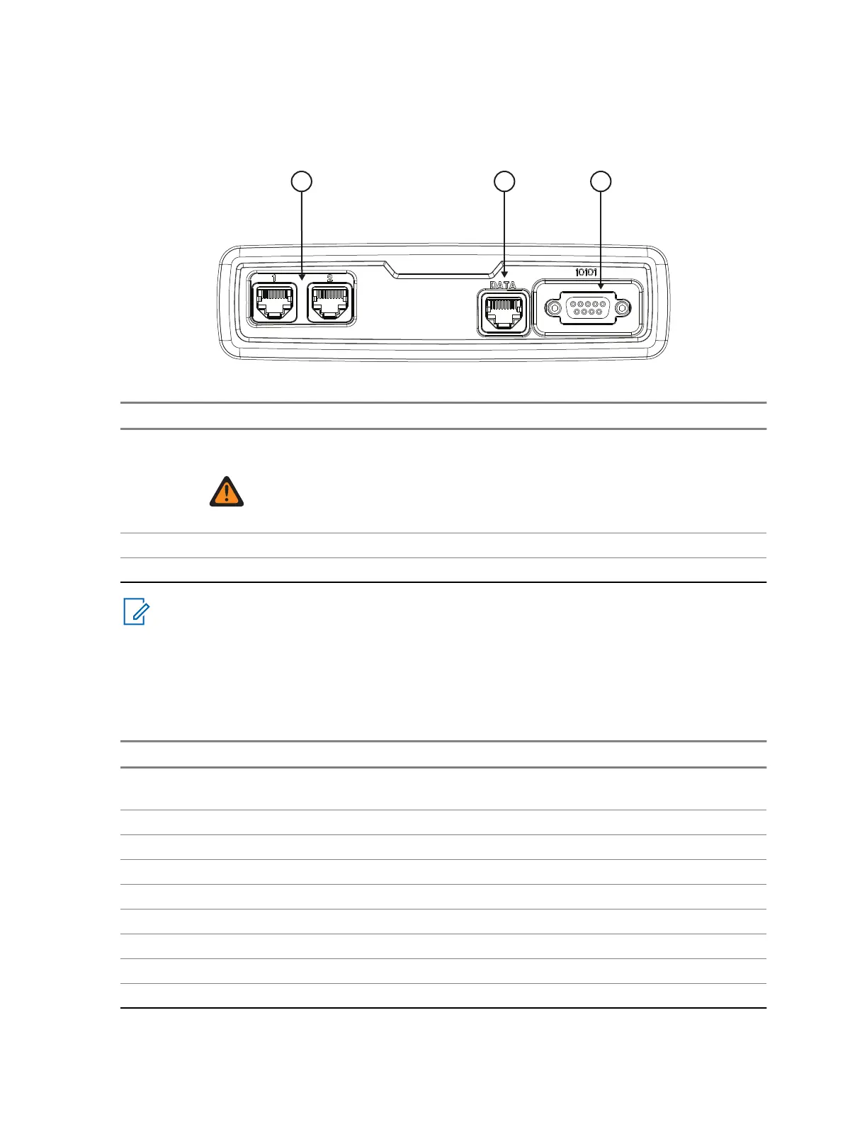
Figure 59: Ethernet Expansion Head Enhanced – Front View and Connector Location
Number Description
1 Two 10–Pin Ethernet Connectors. (Connectors to the Control Heads or Ethernet Ex-
pansion Head).
WARNING: Ethernet Expansion Heads are only compatible with Ethernet
Remote Heads. Do not mix Ethernet control head with non-Ethernet control
heads.
2 10–Pin Connector
3 9–Pin subD Connector
NOTICE: Use appropriate 10-Pin Ethernet cable to connect Control Heads or Ethernet
Expansion Head. Do not use TELCO cables.
5.5.1
Ethernet Control Head Interfaces
Table 54: Pin Assignment of the 10-Pin RJ50 Port 1 and Port 2 Connector – Ethernet Expansion Head
Pin Function Description
1 FLT_A+ (12 V) This is the voltage supply for EEH from power supply or bat-
tery
2 TX_P_P1 Ethernet transmit positive line, TX+
3 TX_N_P1 Ethernet transmit negative line, TX-
4 RX_P_P1 Ethernet receive positive line, RX+
5 GND Main board GND
6 GND Main boards GND
7 RX_N_P1 Ethernet receive negative line, RX-
8 CH_ON_OFF_OUTX_5 V ON/OFF control line Transceiver to Control Head
9 CH_ON_OFF_INX_5 V ON/OFF control line from Control Head to Transceiver
Table continued…
68015000181-LB
Chapter 5: Connectors and PIN Assignment
Send Feedback 101
 Loading...