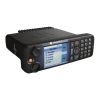
See the following tables for the Pin assignments of the 10-PIN Audio Connector and the RJ50
Connector.
Table 63: Pin Assignment of the 10-Pin Audio Connector – Telephone Style Control Head
PIN Function Description
1 EXT_PWR_12 This is the external voltage supply (12 V or 24 V) from power
supply or battery for external speaker
2 PTT2 CPS configurable GPIO
3 PTT1 External PTT (for HF MIC 2)
4 EMERGENCY_FT_SW Emergency signal line from external MIC
5 EXT_MIC External MIC input line
6 GND Main board GND
7 SPKR+ Output to External Speaker
8 SPKR- Output to External Speaker
9 1-WIRE 1-Wire
®
bi-directional serial bus for accessories ID identifica-
tion
10 Analog Ground Analog Ground
Table 64: Pin Assignment of the 10-Pin RJ50 Connector – Telephone Style Control Head
PIN Function Description
1 FLT_A+ (12 V) This is the voltage supply for the Control Head from power sup-
ply or battery. The maximum current is 300 mA
2 ETH_TX_POS Ethernet transmit positive line, TX+
3 ETH_TX_NEG Ethernet transmit negative line, TX-
4 ETH_RX_POS Ethernet receive positive line, RX+
5 GND Main board GND
6 GND Main board GND
7 ETH_RX_NEG Ethernet receive negative line, RX-
8 CH_ON_OFF_OUT1_5V ON/OFF control line from Transceiver to Control Head
9 CH_ON_OFF_IN1_5V ON/OFF control line from Control Head to Transceiver
10 FLT_A+ (12 V) This is the voltage supply for the Control Head from power sup-
ply or battery. The maximum current is 300 mA
68015000181-LB
Chapter 5: Connectors and PIN Assignment
112 Send Feedback
 Loading...