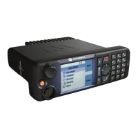
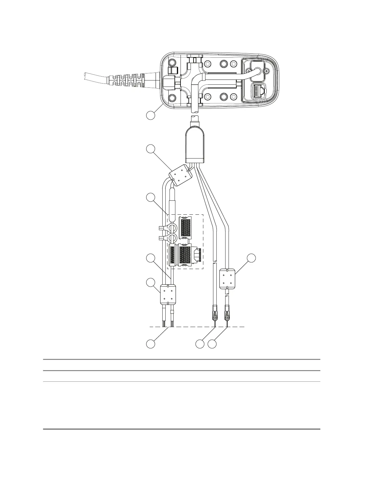
Figure 26: Accessories Expansion TSCH Y-Cable
Number Item
1 Telephone Style Control Head
2 Ground Wire and External Power Wire, Input supply 12 V/24 V: 2A. These connec-
tions correspond to P3 and P4 detailed in Figure 72: TSCH Y-Cable Pin Diagram on
page 114 which provides the Pin Diagram of PMKN4134_. P3 is the 12/24V positive
DC supply input and P4 is the Ground. This supply is for the Audio Power Amplifier
and is required to connect a Loudspeaker is to the TSCH. Note this is the only Power
connection that allows 12 V or 24 V operation all other Power supplies must be 12 V.
Table continued…
68015000181-LB
Chapter 4: Radio Installation
66 Send Feedback
 Loading...