Bus Operation
7-103 MC68030 USER’S MANUAL MOTOROLA
State changes occur on the next rising edge of the clock after the internal signal is valid. The
BG
signal transitions on the falling edge of the clock after a state is reached during which G
changes. The bus control signals (controlled by T) are driven by the processor, immediately
following a state change, when bus mastership is returned to the MC68030.
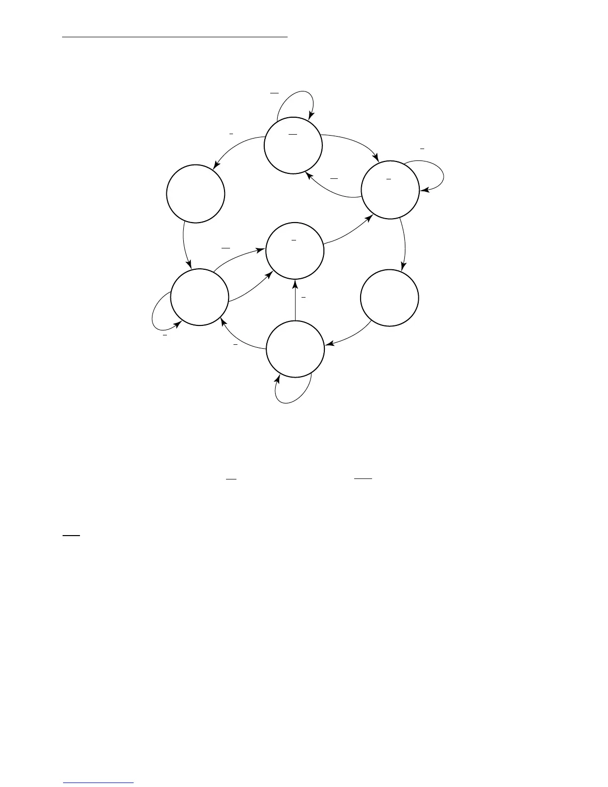
State 0, at the top center of the diagram, in which G and T are both negated, is the state of
the bus arbiter while the processor is bus master. Request R and acknowledge A keep the
arbiter in state 0 as long as they are both negated. When a request R is received, both grant
G and signal T are asserted (in state 1 at the top left). The next clock causes a change to
state 2, at the lower left, in which G and T are held. The bus arbiter remains in that state until
acknowledge A is asserted or request R is negated. Once either occurs, the arbiter changes
to the center state, state 3, and negates grant G. The next clock takes the arbiter to state 4,
at the upper right, in which grant G remains negated and signal T remains asserted. With
acknowledge A asserted, the arbiter remains in state 4 until A is negated or request R is
Figure 7-61. Bus Arbitration State Diagram
RA
RA
XX
RA
RA
RA
XX
RX
RA
XA
RA
RX
XA
RA
GT
STATE 1
GT
STATE 0
GT
STATE 4
GT
STATE 5
GT
STATE 6
GT
STATE 2
GT
STATE 3
XX
R - BUS REQUEST
A - BUS GRANT ACKNOWLEDGE
G - BUS GRANT
T - THREE-STATE CONTROL TO BUS CONTROL LOGIC
X - DON'T CARE
NOTE: The BG output will not be asserted while RMC is asserted.

 Loading...
