Chapter 9 Troubleshooting
This chapter contains the troubleshooting flowchart diagrams for the Overall radio and for the
Controller section of the radio as well as the Control Heads.
Troubleshooting flowcharts for the RF section will be found in Volume 2a, 2b, 2c, 2d or 2e of this
manual depending on the frequency range.
Refer to the SECURENET option service manual (part number 68P81083C25) for troubleshooting
information and troubleshooting flowchart diagrams for the SECURENET Option for the radio.
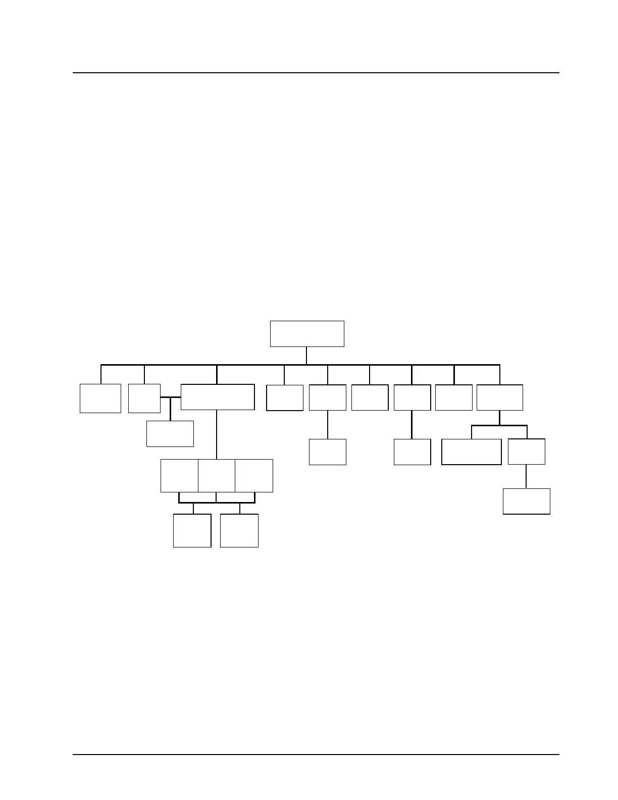
The following chart will give you an overview of the complete set of troubleshooting charts available
for servicing a radio.
Troubleshooting Charts Overview
CHART 1-5
RX AUDIO
RX AUDIO
SIMPLIFIED
SCHEMATIC
CHART 1-3
ON/OFF
RADIO VOLTAGE
SIMPLIFIED
SCHEMATIC
CHART 1-9
CLOCK
DISTRIBUTION
CHART 1-13
POWER
CONTROL
CHART 1-10
SB9600
BUS RX
CHART 1-11
SB9600
BUS TX
SB9600
VOLTAGE
TABLE
SB9600
BUSY
SIMPLIFIED
SCHEMATIC
SB9600
SIMPLIFIED
DIAGRAM
TX AUDIO
SIMPLIFIED
SCHEMATIC
CHART 1-6
SIGNALLING
CHART 1-4
TX AUDIO
CHART 1-7
DC
DISTRIBUTION
CHART 1-8
CONTROL
HEAD
CHART 1-1
OVERALL RADIO
CHART 1-2
FAILURE CODES
3 SHEETS
RF BAND
SPECIFIC
CHARTS
(VOL 2)
CHART 1-12
GPIO
CHART 1-9
CLOCK
DISTRIBUTION
Refer to the IC Troubleshooting
Procedure before replacing any ICs.
MAEPF-25961-O

 Loading...


