December 6, 2004 68P81083C20-D
9-2 Troubleshooting: Troubleshooting Chart 1-1, Overall Radio
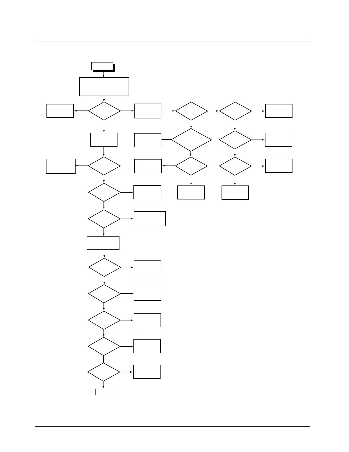
Troubleshooting Chart 1-1, Overall Radio
GOTO
Signalling
Chart 1-6
GOTO
Band Specific
RX IF
GOTO
Band Specific
RX Front End
GOTO
RX Audio
Chart 1-5
Connect signal generator
to antenna connector.
Set to channel frequency.
Check frequency
tuning using RSS.
GOTO Band Specific
Synthesizer Chart
GOTO
TX Audio
Chart 1-4
GOTO
DC Distribution
Chart 1-7
GOTO
Control Head
Chart 1-8
Attach known good
control head using
control head
extender cable
Check TX power
tuning with RSS.
GOTO Power Control
Chart 1-13.
Radio Setup
A+ = 13.4V, Accessory Connector
plugged in, Control Head plugged in,
Emergency Jumper in place
(Speaker Jumper in place Model 1 only)
Put the radio
in CSQ test mode
(Note 1 and 2)
GOTO
Failure Code
Chart 1-2
Pressing
On/Off Button, errors
on display?
Display
OK?
No
No
Errors
Yes
Yes
Yes
No
No
Yes
No
No
No
No
Yes
Yes
Yes
No
Yes
No
No
Display
Yes
Errors
IF remote
cable, do all lines
have continuity and all
lines free of shorts
to other lines
TX power
OK?
TX deviation
OK?
TX output
centered on
frequency?
Press
monitor button
on control head. Audio
from speaker?
Sensitivity
OK?
Audio distortion
<5%?
Radio
decoding
PL/DPL?
13.4V on
J0405-18?
Replace
Cable
No
Repair or
Replace
J0405
No
J0405
OK?
Yes
Yes
Yes
GOTO
DC Distribution
Chart 1-7
Yes
No
13.4V on
J0405-17?
GOTO
On/Off
Chart 1-3
GOTO
SB9600 Bus RX
Chart 1-10
Yes
No
Pressing
On/Off Button
creates pulse on
J0405-9?
Yes
GOTO
GPIO
Chart 1-12
END
No
Emergency
Horn and Lights
OK?
START
NOTE: Button press is to defeat squelch. Audio may come through
without button press depending on squelch level set.
Note 1. Power up the radio and press the
monitor button five times.
Note 2. See Band Specific TX Troubleshooting
Chart for proper setup.
MAEPF-25945-O

 Loading...


