68P81083C20-D December 6, 2004
Disassembly & Reassembly and Replacement Procedures: Disassembly to Transceiver Board Level
Mid Power Models
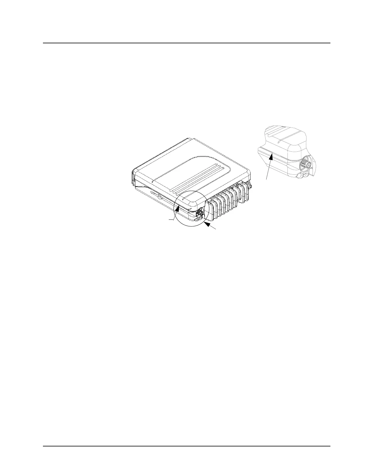
1. Insert a wide flat-blade screwdriver or like instrument in the recess area on the side of the
radio near the RF and DC connector end (see Figure 5-3).
2. Pry the cover off the chassis by pushing the handle of the screwdriver in and toward the chas-
sis. This will disengage the snap between the cover and chassis.
3. Repeat Step 1 and Step 2 for the opposite side of the radio.
Figure 5-3. Removing the Top Cover - Mid Power Models
Remove the Cavity Shield
Low Power Models Only
NOTE: Eight tabs hold the cavity shield to the chassis. The cavity shield is the retaining device for the
transceiver board and also provides the pressure to heat dissipating devices attached to the
chassis.
1. Note the location (see Figure 5-18) of the cover gasket on chassis before removal. Remove
the cover gasket from the chassis.
2. Loosen the cavity shield by prying each of the eight tabs away from the chassis. Release the
four tabs on one side first and then repeat the operation on the other. Be careful not to pry the
tabs any more than is necessary to free them from their respective retaining posts (see Figure
5-4).
3. Pull straight up on the cavity shield.
Disengage Snap here
and on other side
Disengage Snap here
Detail “A”
See Detail A

 Loading...


