December 6, 2004 68P81083C20-D
5-10 Disassembly & Reassembly and Replacement Procedures: Disassembly of the Control Head
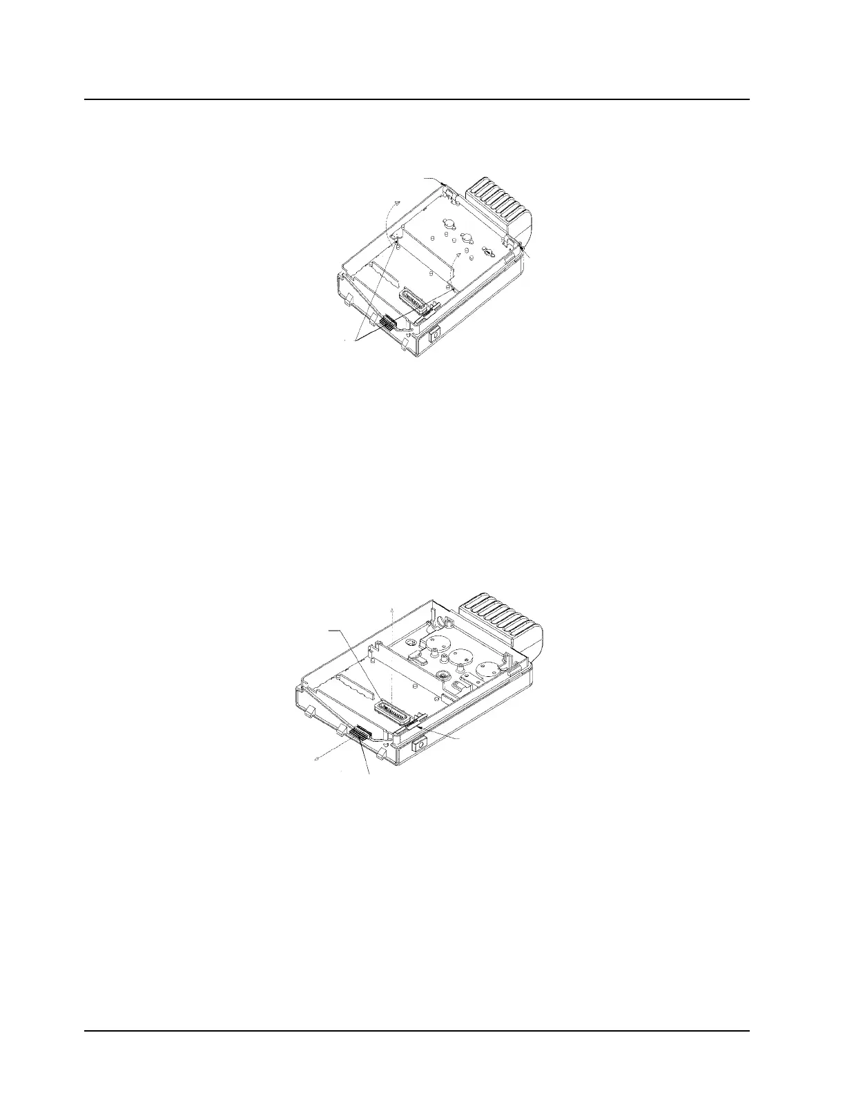
4. Once the connectors are disengaged, remove the PA Board from the chassis by pulling edge
of board up and away from fin (back) side of radio.
Figure 5-14. Removing the PA Board
Remove the RF Board
1. Remove the 18 position connector by pulling it straight out from the chassis taking care not
the bend the leads.
2. Remove the Audio PA Clip by inserting a flat-blade screwdriver under the clip´s extended tab,
pivoting off the top of the underlying wall, and gently prying the clip upward.
3. Unscrew the 7 screws that hold the RF board in place using a T-10 Torx driver.
4. Carefully remove the RF board from the chassis by pulling straight up on the 25 D connector.
Figure 5-15. Removing the RF Board
Disassembly of the Control Head
NOTE: For details please refer to the relevant control head exploded views on pages 10-7 through
10-9.
Dash Mount Versions
Follow steps 1-4 on page 1 to remove the control head.
Pry Clip off here
Pry Clip off here
Disconnect PA board
from these two RF
connectors
25!D!Connector
Pull!board
straight!up
Pry!off!Audio!PA!clip!here
18!Position!Connector
Pull!Connector
straight!out

 Loading...


