December 6, 2004 68P81083C20-D
5-16 Disassembly & Reassembly and Replacement Procedures: Transceiver Reassembly High Power Models
Transceiver Reassembly High Power Models
NOTE: Replace all gaskets at each servicing to ensure proper sealing of unit.
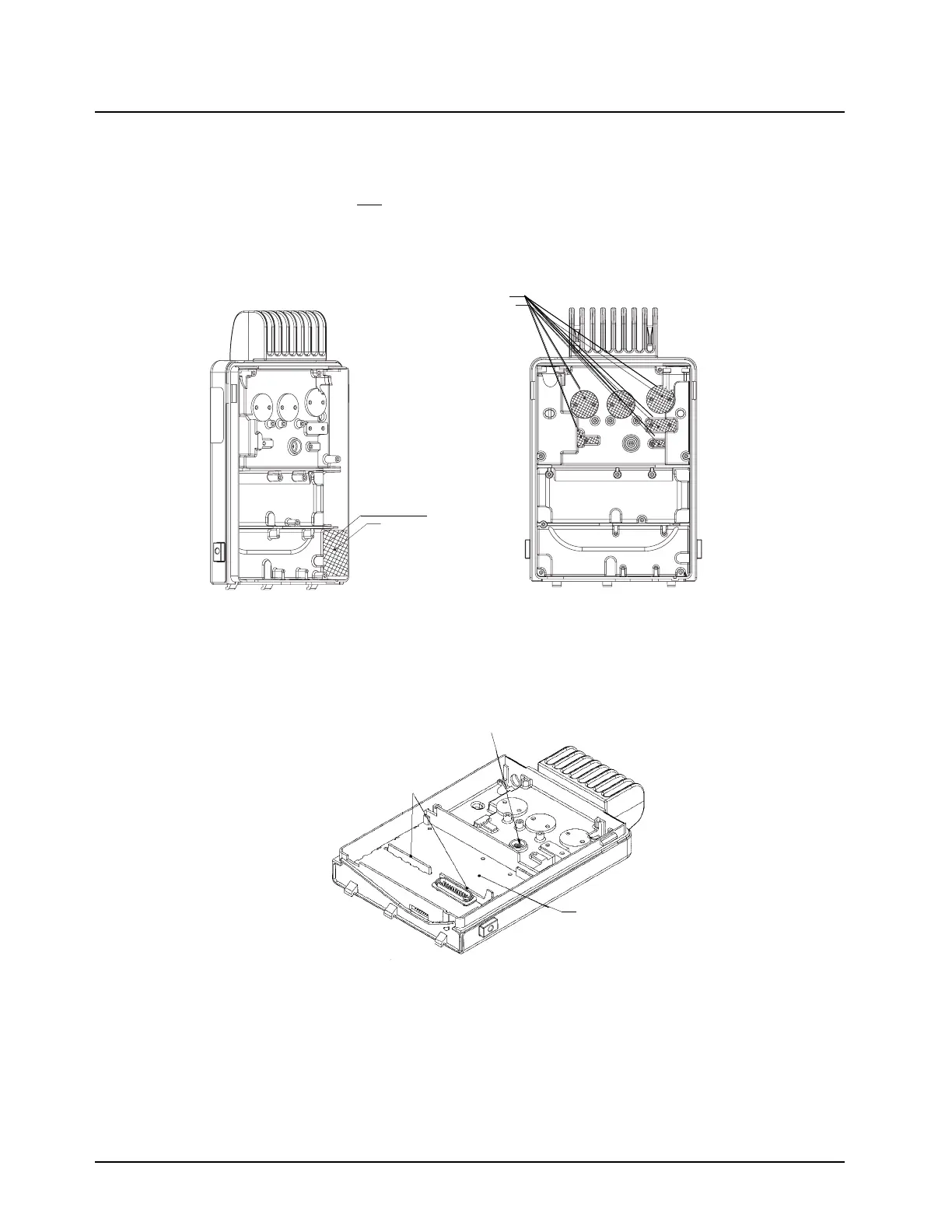
1. Inspect and reapply a thin
coat of thermal compound as necessary to the heatsinking pads,
voltage regulator and Audio PA areas in the chassis per Figure 5-19. A thick coat of thermal
compound may negatively effect heat sinking.
Figure 5-19. Wakefield / Thermal Compound Application Area
2. Insert the transceiver board placing board slots over locating features in chassis. Be sure the
board is sitting flush on the chassis mounting surface.
Figure 5-20. Inserting Transceiver Board
3. Replace the 25-D connector gasket on the transceiver board.
4. Replace the RF and power connector gaskets on the PA board.
5. Install the PA board carefully at an appropriate angle (approximately 30
o
) to the chassis con-
necting the 2 and 12 pin connectors to the RF board.
6. Install the 2 PA connector retaining clips over the RF and power connectors and chassis wall.
Apply Thermal Compound
to this portion of
chassis wall
Apply Thermal Compound
to these raised areas
Chassis
locating!features
Spring!Diode
Transceiver!board

 Loading...


