68P81083C20-D December 6, 2004
Diagrams and Parts Lists: Exploded View Parts List, Control Head Model III 10-9
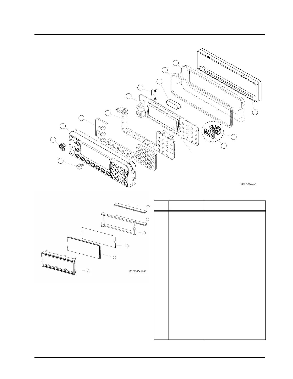
Exploded View Parts List, Control Head Model III
ITEM
NO.
MOTOROLA
PART NO. DESCRIPTION
1 1502455Y05 Housing, Back
2 3202462Y03 Gasket, Housing
3 4602100U01 PCB Retainer
4 HCN4059
PCB Assembly
a
a Radios with SDLN4193 may use HCN4059 as replacement
5 6102081U04 Light Guide
6 7505242Z04
or 7505242Z04
Keypad, std. with text
Keypad, without buttons for use with
Replaceable Pushbuttons
7 1502100U15 Housing, Control Head Model III
8 3685804A02 Volume Knob
9 7608133K01
Ferrite Plate
2
10 1580365K01
Shroud, white
b
b Parts have been eliminated
11 0704779P01 Retention Frame
12 2802102U01 Connector, Elastomeric - Gray
13 2802101U01 Connector, Elastomeric - Pink
14 0702084U02 Frame, LCD
15 9102102U02 Reflector Sheet
16 7202076U03 Display Glass
17 1302085U01 Bezel
18 3280542K01 Adhesive Pad
19 see Chapter 5 Replaceable Pushbutton
11
10
9
19
8
7
6
5
4
3
18
2
1
LCD:!see
detail!below
13
14
15
16
17
18
LCD!Detail

 Loading...


