68P81083C20-D December 6, 2004
Basic Maintenance: Antenna/Power Connector Replacement Procedure 2-5
7. Inspect solder joints. The solder should not “ball-up” over leads. There should be a uniform fil-
let. The joints should be shiny and not dull in appearance.
8. Remove retaining clips. Unscrew board. Take board out of chassis.
9. Inspect for uniform solder fillet around leads on heavy side of board. Ensure that there is not
excessive solder around leads. If excessive solder exists, carefully remove it with the solder-
ing iron.
10. Reassemble board into chassis per the Reassembly/Assembly procedure on the previous
pages based on the power level being repaired.
Using temperatures higher than 750°F/400°C will cause the
modular ground rings to pull off the board around pins and
cause the board irreparable damage.
If solder joint does not exhibit these characteristics, the joint
will contain a cold solder and/or voids that could damage the
Power Amplifier portion of the radio.
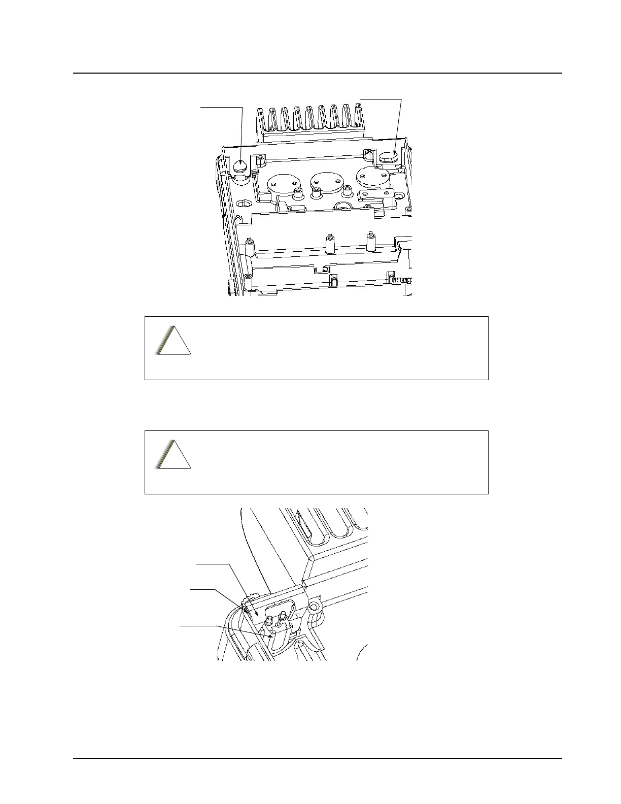
Power Connector
Opening
RF Connector
Opening
-
-
!
a u t i o
!
a u t i o
Retaining
Clip
Chassis
Wall
Connector

 Loading...


