Section 5
RADIO INFORMATION
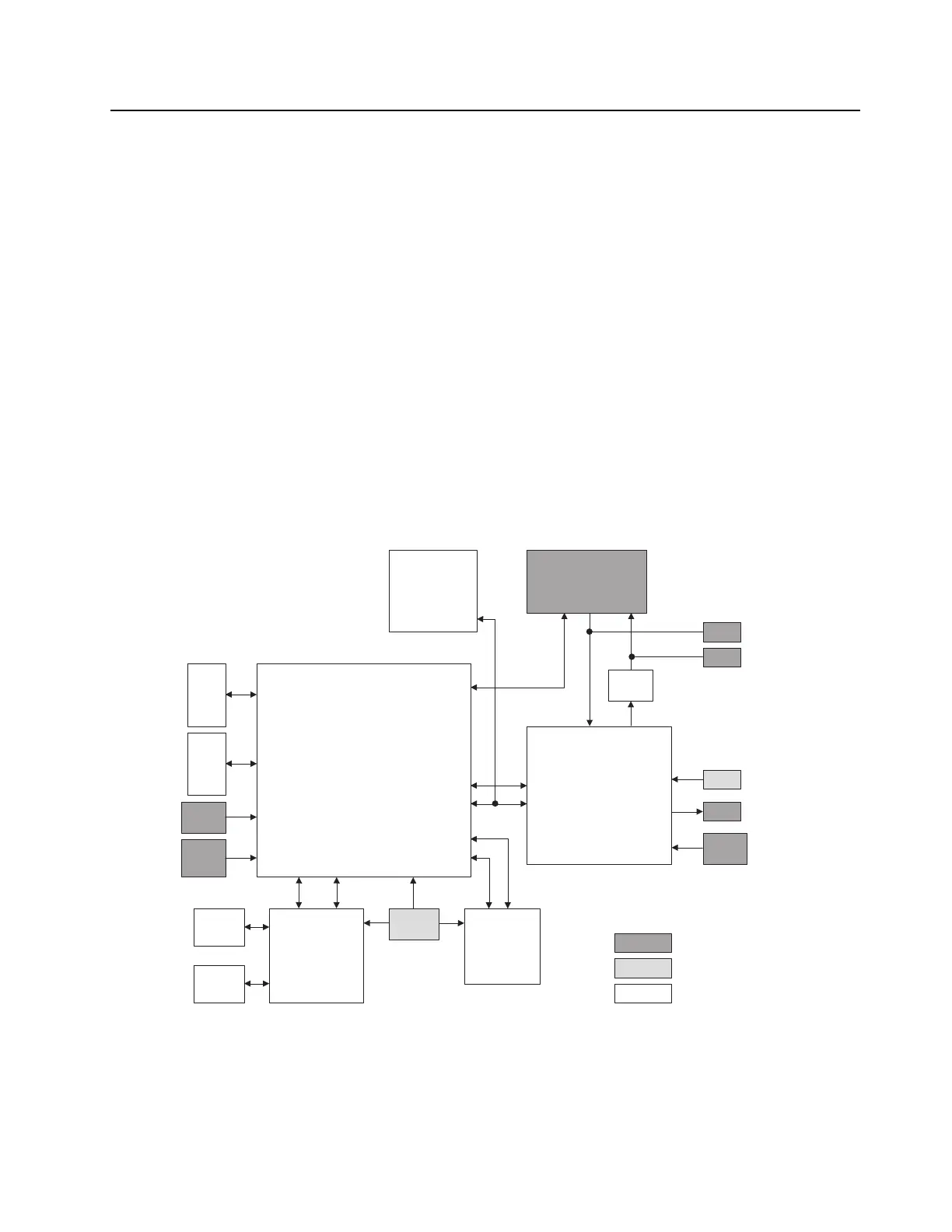
1.0 General Controller Block
The controller section consists of a host processor, Power & Peripheral management (PMIC) IC, with
supporting flash and RAM memory devices for the radio operation. In addition to these,
Accelerometer, Wireless connectivity chip, Location & Position chip, Option board, color display,
matrix keypad, audio amplifiers, backlighting scheme, and status indicator, from the controller section.
The host processor, masters all the tasks of the controller section in conjunction with the peripheral
management processor within the PMIC IC.
The system is powered from a 7.5V battery supply and the power converters, both external and
internal to the PMIC provides the necessary power to the above processors and peripherals of the
system. The clock generation for the system operation and wireless connectivity chip are generated
from two different TCXOs for the performance requirement.
Figure 5-1. Controller Block Diagram
External Input/Output
Clock
Other blocks
Microcontroller
mDDR
NAND
Flash
Power
Management
LED
ON/OFF
/VOL
Knob
Freq
Knob
PTT/Sid
e/EMER
Button
TCXO
19.2MHz
RFIC
BT/GPS
XTAL
TX
Front-end
RX
Front-end
Audio
PA
GPIO
GPIO
SPI1 SSI1
Option
Board
SSI2
UART1
AUDIO SSI
SPI0
Accessory
Interface
USB
MIC SPKR
MIC
SPKR
 Loading...