General Controller Block 5-3
1.2 Receiver
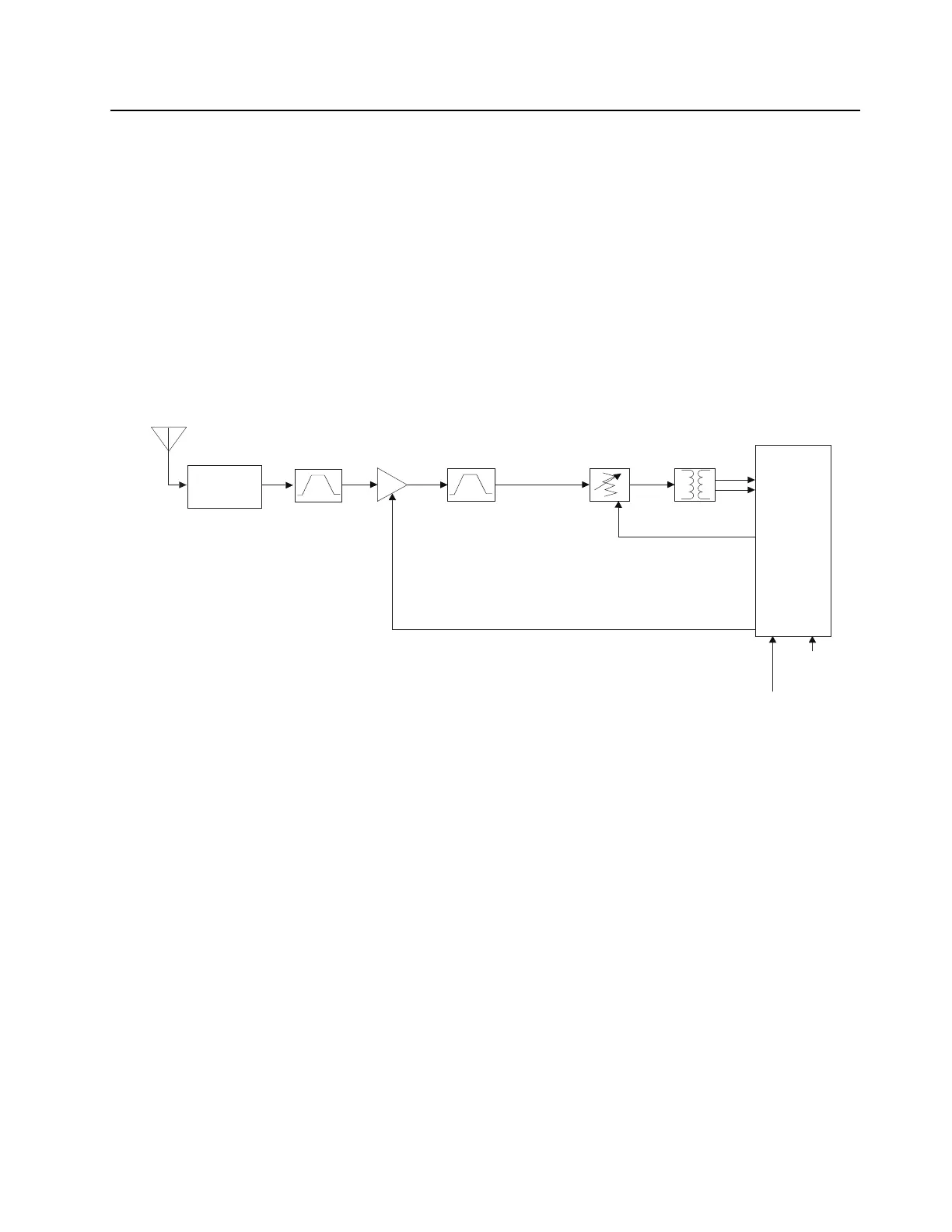
The receiver front end is defined as being the circuitry from the antenna input to the RFIC (U0001).
The received signal from antenna will pass through the antenna switch. The antenna switch provide
selection between receive and transmit path. The receive signal which was routed to the receive path
will then flow through a bandpass filter of 403MHz to 527Mhz. The output signal of the bandpass filter
will then fed into the low noise amplifier (LNA).
In VHF/UHF, the LNA provide 13 – 15dB gain depending on the RF frequency. After being amplified,
the RF signal is further filtered by a bandpass filter. Depending on the level of the interference signal
and mode of operation, step attenuator (U0480) will be trigger to provide protection to the RFIC from
saturation. The Balun (T0490) is a 1:1 transformer providing single ended to differential
transformation. Output of the Balun will then be fed to the RFIC for back end processing.
Figure 5-3. Receiver
Receiver Front End
*38.4 MHz
Reference
Clock
RFIC
Balun
Band Pass Filter
Step Attenuator
LO from FGU
Antenna
Antenna
Switch
HT
LNA
Band Pass Filter
RF_Step
RX_EN
*Note
For 800/900, 19.2 MHz will be used for REF_IN
For VHF/UHF, 38.4 MHz will be used for REF_IN
 Loading...