5-6 General Controller Block
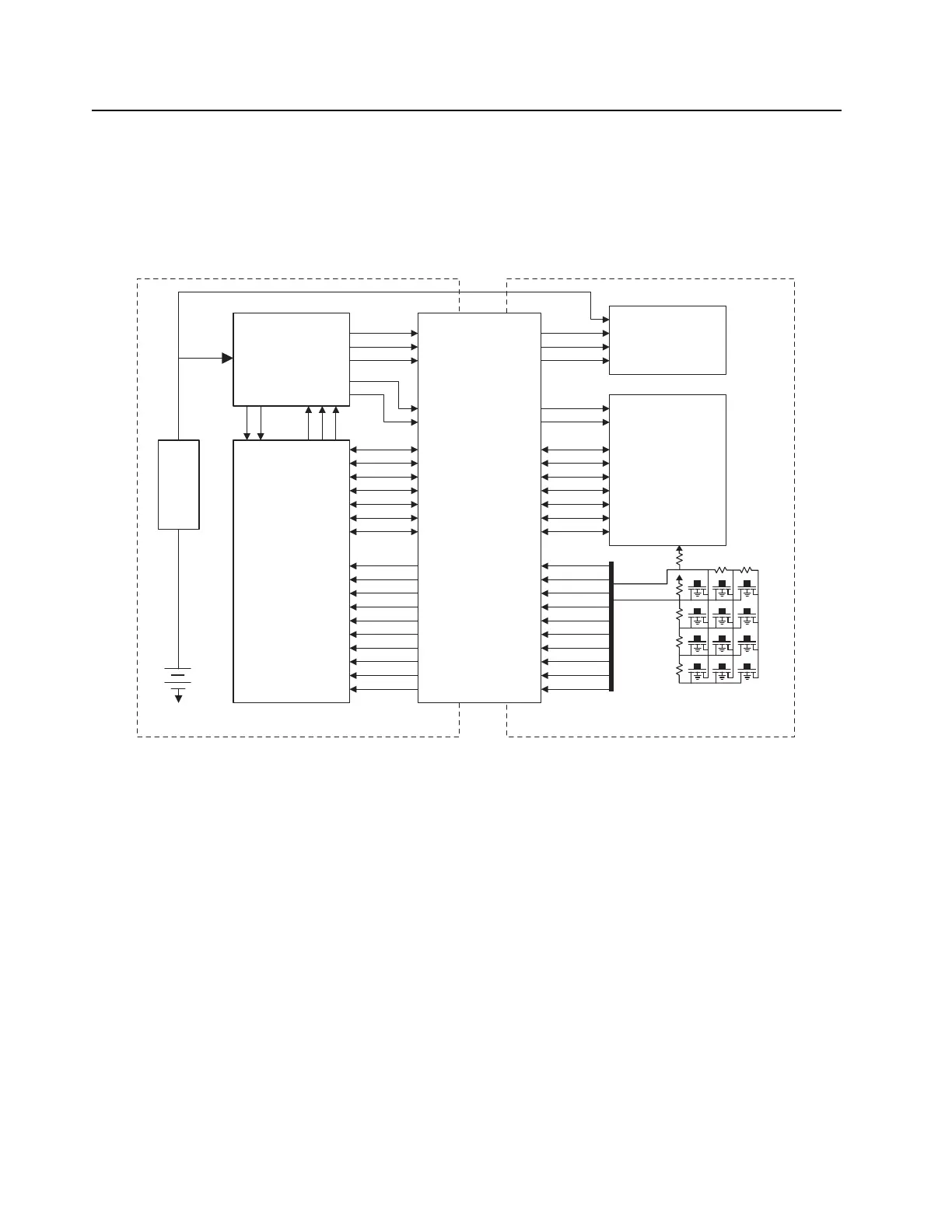
1.5 Keypad and Display Block
The LCD display module and keypad interfaces communicates directly to the host processor on the
main board. To communicate and control the display driver, four control lines run between the main
board and the display board. The LCD is reset from host processor through UART type connection.
The keypad interfaces communicate to host processor by using a Row/Column resistor ladder
through GPIOs.
Figure 5-6. Full Keypad
Power
& Peripheral
Management
Host
Processor
LCD Driver
DISPLAY_CE_SHIELD
Keypad Col
Keypad Row
DISPLAY_CMD
ID_TE
LCD_RESET
NRD_E
NWR_RNW_SHIELD
LCD_D<7..0>
KPSINK
MDSINK1
MDSINK2
KEYPAD_COL4
KEYPAD_COL3
KEYPAD_COL2
KEYPAD_COL1
KEYPAD_COL0
KEYPAD_ROW4
KEYPAD_ROW3
KEYPAD_ROW2
KEYPAD_ROW1
KEYPAD_ROW0
Main Board Keypad Board
Connector
LCD & Keypad
Backlight
1.8V
3.3V
3.6V
Switcher
 Loading...