5-4 General Controller Block
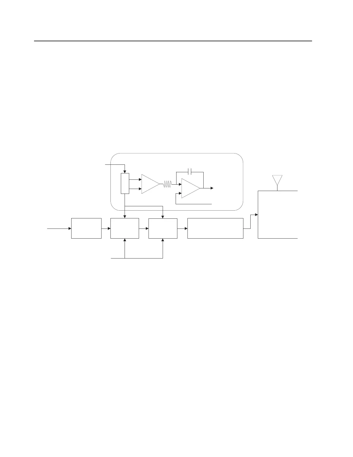
1.3 Transmitter
The transmitter contains five basic circuits: power amplifier, antenna switch, harmonic filter, 50 ohms
RF switch & antenna matching network, and power control.
The power amplifier is a 3-stage discrete design consisting of a Pre-driver, Driver and final PA. The
gain of both Driver and final PA are controlled by Vcontrol from power control circuit.
The antenna matching network is used to match the antenna's impedance to the 50 ohms RF switch.
The transmitter power control uses discrete integrator (U0900) approach, the first stage is an I-V
converter which converts current drained by Power Amplifier Driver (Q0710) and Power Amplifier
Final (Q0720) across R0905 into a voltage drop and the second stage is an integrator used to control
and shape the output Vcontrol to bias both PAs.
Figure 5-4. Transmitter
PA Predriver
PA
Driver
Tx Injection
Vcontrol
PA
R0905
Current to
Voltage
Integrator
Vcontrol
Harmonic Filter &
Antenna Switch
RAW B+
Tx Ramp
50 ohms
RF switch &
Antenna Matching
Network
Power Control
 Loading...