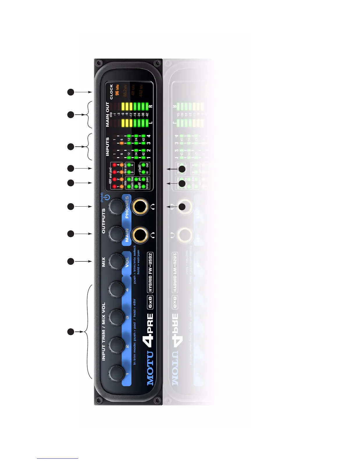
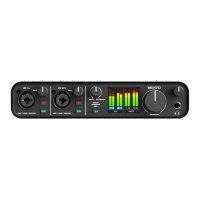
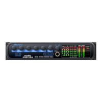
Quick Reference: 4pre Front Panel
1. These four Precision Digital Trim™ rotary encoders
provide triple-function control over the trim level, mix
volume, and pan of the XLR/TRS combo jacks on the rear
panel. Push the MIX knob (2) repeatedly to cycle among
the four separate mixes and trim mode. The LEDs (11)
indicate the current mix, or trim mode. When a mix is
active, push and hold the MIX knob to toggle between
volume and pan control, as indicated by the LEDs (11).
When in trim mode, use the knob and input level meters
(7) to calibrate the input signal level. These knobs
provide +60 dB and +22 dB of boost, respectively, for
the mic (XLR) and instrument (TRS) input jacks. Adjust-
ment can be made in approximately 1 dB increments. All
four jacks have preamps, so you can plug in just about
anything: a microphone, a guitar or even a synth. For +4
dB signals, push the knob (1) to engage the -20 dB pad.
For the XLR mic input, push and hold the knob to toggle
48V phantom power.
When in mix mode, use the knob to control the jack’s
input volume or pan (as indicated by the LEDs, 11) for
the currently selected mix.
2. This multi-function knob controls volume of the 4pre’s
four mix busses (11). Push the knob repeatedly to cycle
among the four mix busses, as indicated by the LEDs
(11). When a mix is active, push and hold the VOL knob
to toggle the individual channel knobs (1,2,3, and 4)
between volume and pan control, as indicated by the
“pan” LED (11), where on is pan and off is volume.
3. Turn the MAIN knob to control the main outs and the
headphone jack below the knob, which mirrors the main
outs.
4. Turn the PHONES knob to control the headphone jack
volume below it. When power is off, push the PHONES
knob to power on the 4pre; push and hold to turn it off.
When connected to the computer via FireWire, the 4pre
is powered by its FireWire connection. When connected
via USB, it must be powered with the included DC power
adapter.
5. These eight LEDs indicate whether the -20 dB pad or 48V
phantom power is enabled or disabled for the corre-
sponding mic input (1).
6. The “line out” LEDs provide signal activity on line outputs
3 and 4.
7. The four input meters provide five-segment metering for
the mic inputs, ranging from -42 dB to -1 dB.
8. The MAIN OUT meters provide ten-segment ladder LED
metering for the stereo main outputs, ranging from
-42 dB to clip.
9. Indicates the current operational sample rate.
10. The S/PDIF activity LEDs indicate signal presence for
input and output.
11. The Mix LEDs indicate what is being controlled by the
mix/trim knobs (1 and 2). Push the MIX knob (2) repeat-
edly to cycle among the four separate mixes and trim
mode. When a mix is active, the knobs control input
levels for the current mix. Push and hold the MIX knob
(2) to toggle between volume and pan control (pan LED
off and on, respectively).
When trim mode is selected, the knobs control input
trim levels.
12. This is a standard quarter-inch stereo headphone jack.
From the factory, it operates as its own output pair. But it
can be programmed to mirror any other output pair
(digital or analog). See “Phones Assign” on page 34. Use
the volume knob above to control its level.
21
10
3 4 5 6 7 8 9
1112