Page 10
5. Apply a film of grease to the splines on the inside of the
gear balI (10). Install gear ball on connecting rod (38), with
counter-bored end (end without splines) first on connecting
rod. Gear ball should slide freely against shoulder on
connecting rod. Place lock nut (9) on connecting rod and
tighten against gear ball. Apply grease to spherical surfaces
and teeth of gear ball.
6. Apply grease to the teeth of the ring gear (8), and slide
ring gear onto the gear ball. When ring gear is in place,
keyways should be facing the lock nut end of connecting rod.
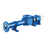
7. Apply a thin coating of grease to the spherical surface
of the thrust plate (6) already installed in the rotor head. Fill
the recessed area in the rotor head with grease.
8. Slide the gear joint shell (39) over the connecting rod
and assembled gear joint components, being careful to seat
the outside diameter of the gear joint seal (13) in the end of
the gear joint shell (39). The two tapped holes in the gear
joint shell should be in line with one of the keyways in the
ring gear.
9. Place keys (7) in the keyways in the ring gear. Check to
insure the tapped holes in the side of the gear joint shell are
aligned with one of the keyways.
10. Align the keys in the ring gear with the keyways in the
rotor head. Slide assembled gear joint shell onto the rotor
head, checking to be sure the keys are properly engaged in
the rotor head and ring gear. The shallow hole in the rotor
head should be aligned with the first threaded hole in the
outside of the gear joint shell. Thread the setscrew (S) into
the threaded hole in the shell until light contact is made with
the hole in the rotor head.
11. Place O-ring (41) into step in gear joint shell. Align
holes in head ring (42) with six threaded holes in end of gear
joint shell and install stainless socket head screws (T).
Tighten the six socket head screws evenly, checking to in-
sure O-ring (41) remains in place. When tightened properly,
a small gap of a few thousandths of an inch may exist be-
tween the shell (39) and head ring (42).
12. Excess grease in the assembly will be purged from the
vent hole while the socket head screws are tightened.
Tighten the setscrew (S) in the shell. Move the free end of
the connecting rod in a circular motion to assure that the joint
is free and assembled properly. This will also help to purge
excess grease from the assembly.
13. Install the stainless steel pipe plug (C) in the
second hole in the shell and tighten.
4-31. Rotor/Stator to Drive End Assembly
1. If not already in place, slip stator clamp rings (36) on
both ends of stator (30), and install retaining rings (35) in
grooves provided on both ends of stator.
2. Place stator gasket (34) in recess in end of suction
housing:
a. On J335 model, stator gasket (34) will be installed
in recess in adapter housing (25B).
b. On F012, G022, H036, and K115 models, stator
gasket (34) will fit recess in adapter flange (25A) and adapter
flange gasket (24A) will fit recess in suction housing.
3. Move the rotor/stator/connecting rod assembly in po-
sition, and insert connecting rod through the suction housing
and drive shaft. Align stator with bore in suction housing, and
slide stator in place, checking to insure that stator gasket
(34) remains properly positioned.
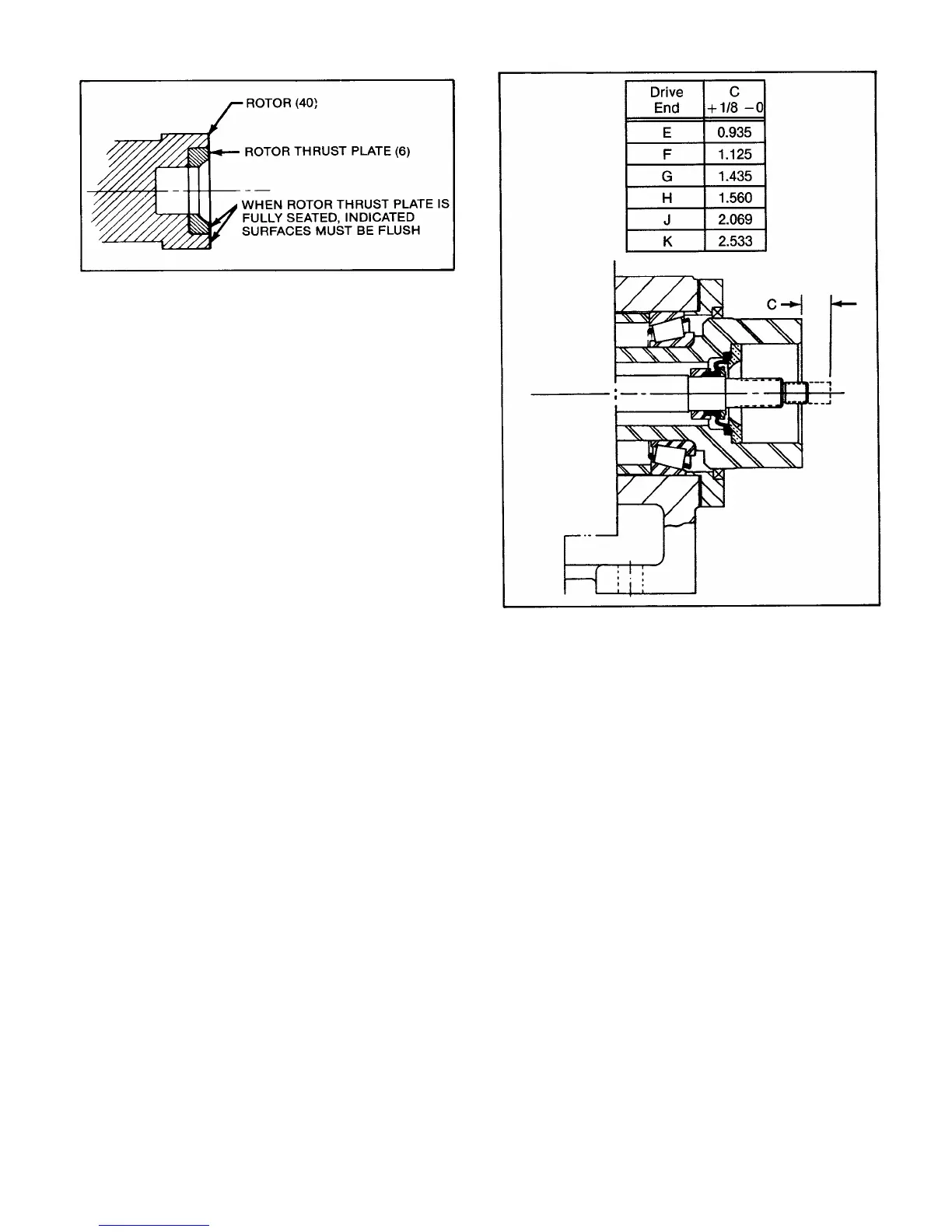
4. Check the dimension “C” between the end of the con-
necting rod and face of the drive shaft as shown in fig. 4-7.
For proper assembly of the drive end gear joint, this
dimension should be no less than that shown in column C,
and should not exceed the amount in column C by more than
1/8 inch. Reposition rotor/stator assembly in or out of suction
housing as required to achieve the proper dimension.
Figure 4-6. Rotor Thrust Plate Seating Detail
Figure 4-7. Gear Joint Installation