4-16. INSPECTION
4-17. Bearings. After cleaning, rotate bearings very slowly
under hand pressure to feel for smoothness and even action.
Never spin a dry bearing. Check for cracks, galling, pitting,
burrs, etc. Replace bearing if there is any doubt concerning
complete serviceability.
4-18. Drive Shaft. Inspect drive shaft (14) for scoring, burrs,
cracks, etc. Replace as necessary.
4-19. Seals. It is sound practice to always replace grease
seals (1 and 19) whenever drive shaft and tapered roller
bearings are removed. Apply Locktite 690 to outside
diameter of both grease seals.
4-20. Packing. It is sound practice to always replace pack-
ing (22) whenever the pump bearing housing is
disassembled.
4.21. Rotor.
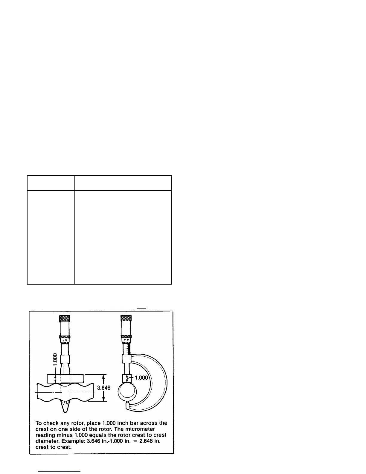
1. To check for excessive wear of rotor (40), measure the
rotor crest-to-crest diameter (see fig. 4-4) and compare with
the following chart:
Rotor
Capacity
Standard
*Crest to Crest Dia. (inches)
008 2.772 + .000/—.004
012 2.676 + .000/—.004
022 3.425 + .000/—.004
036 4.015 + .000/—.004
050 4.015 + .000/—.004
065 4.906 + .000/—.004
090 4.906 + .000/—004
115 5.709 + .000/—.004
175 6.584 + .000/—.004
335 5.800 + .000/—.005
345 7.260 + .000/—.004
620 7.128 + .000/—.005
800 7.658 + .000/— .004
* These dimensions are applicable for AAA trim codes only.
Note: The rotor is designated by the third, fourth and fifth
numbers in the Model Number, i.e., 1G065
G1.
2. If the measured crest to crest diameter is within 0.010
inch of the standard value and is free of deep nicks, gouges,
or other surface defects, the rotor is re-usable.
3. Rotors with crest to crest values 0.011 to 0.050 inch
under the standard values should be replaced. These rotors
can be renewed by chrome plating to standard dimensions
provided that:
a. The key slots are not excessively worn.
b. The rotor surface is not cracked, pitted or deeply
grooved (1/32 inch or more).
c. The base surface metal is not pitted or corroded.
4. Rotors may be sent to Moyno or any other competent
plating shop. Rotors should be stripped and replated to
standard dimensions, then buffed.
4-22. Stator. A worn stator may appear pitted and gouged,
or may appear smooth similar to when new. Performance is
the best measure of rotor to stator fit. If unable to measure
performance adequately, suspected stator wear can be
evaluated by a Moyno sales or factory representative.
4-23. All Other Parts. Check for cracks, excessive wear,
damage to threaded holes, burrs, etc. Replace as necessary.
Replace O-rings and all gaskets at each disassembly and
reassembly.
4-24. ASSEMBLY
The Moyno 2000 pumps are reassembled in the reverse
order of dismantling. The following suggestions are offered:
1. While pump is dismantled, check all gaskets, seals,
packing, and O-rings. Replace all worn items. It is recom-
mended that the gear joint seals (13), gear joint O-ring (41),
and drive shaft O-ring (5) be replaced each time either of the
gear joints is disassembled.
2. During the assembly process, cleanliness is important.
To avoid premature failure, bearings and gear joint compo-
nents must be handled with care and kept clean.
4-25. Lubrication During Assembly
Note: The bearings are lubricated at the factory, and will
only need to be re-lubricated when the shaft/bearing
assembly is completely removed from pump.
1. Bearings. Pack bearings after installation on shaft
(Section 4-28). Lubricant should be packed around all of the
rollers and should completely cover the faces of the races.
The void inside the spacer between the bearings should be
filled approximately half way with lubricant.
2. Gear Joints. Both gear joints should be packed with
lubricant during assembly (Sections 4-30 and 4-32). DO
NOT use zerk fittings to lubricate gear joints after assembly.
The pipe plugs (C) in the drive shaft head, drive shaft, and
gear joint shell are vent plugs and MUST BE REMOVED
during assembly of the gear joints to allow excess lubricant
to vent from the gear joints.
3. Packing. Lubricate packing rings during assembly. Ad-
ditional grease can be added after assembly through the
zerk fittings installed in the side of the stuffing box.
Page 7
Figure 4-4. Measuring Rotor Dimension