Page 26
4-49. FIBER DEFLECTOR OPTION
4-50. OPERATION
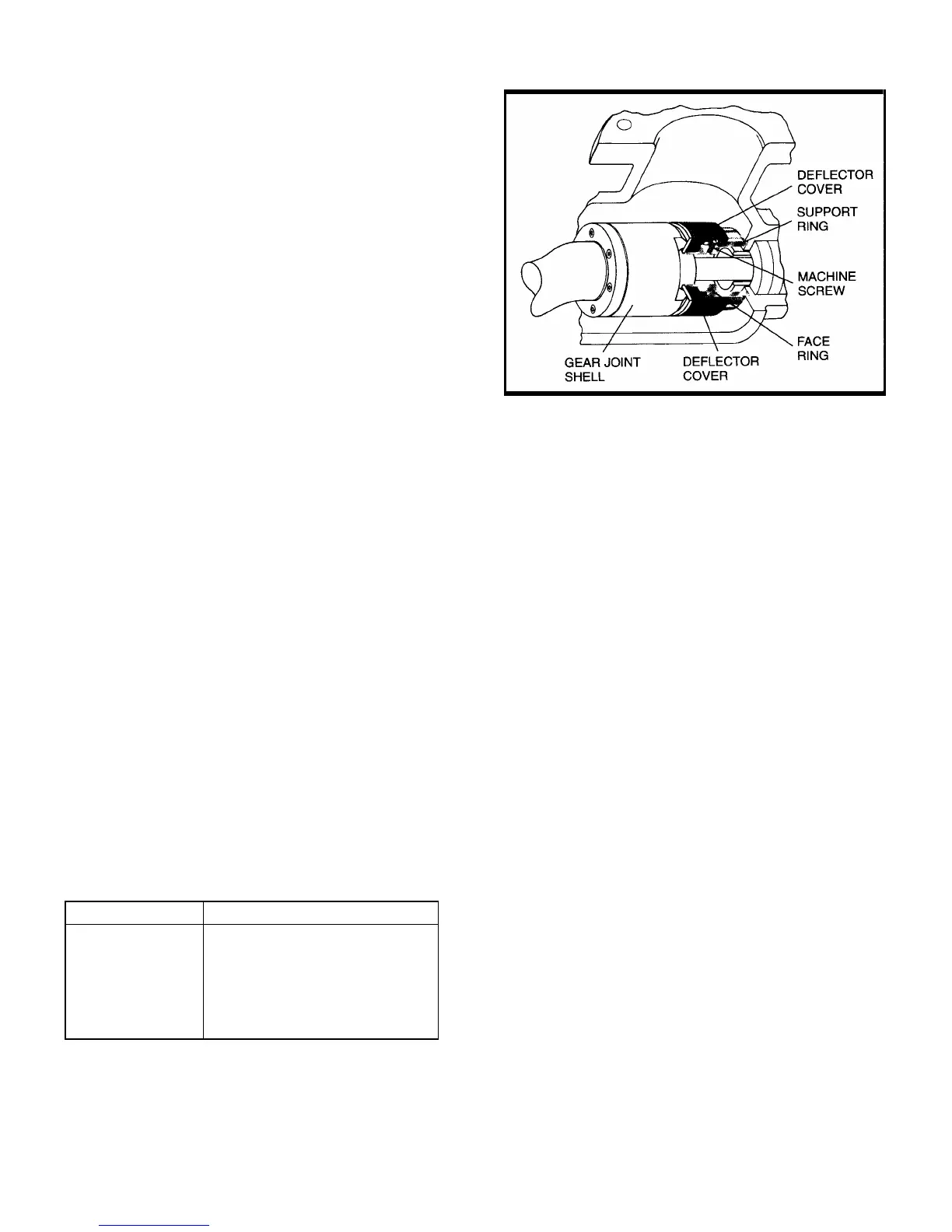
The Moyno Fiber Deflector is designed to prevent an accu-
mulation of rags and stringy material around the connecting
rod and rotor head area of your Moyno 2000 pump. The
Fiber Deflector eliminates the potential for equipment
damage and downtime due to blockage.
The Fiber Deflector operates in a similar way to an end
face-type mechanical seal. The stationary lip of the deflector
cover rides against a polished disk rotating with the gear joint
shell. The deflector cover does not seal fluid from entering
the drive shaft; it only shields debris from wrapping around
the connecting rod.
4-51. DISASSEMBLY/ASSEMBLY
A Moyno 2000 pump purchased from the factory and
equipped with a fiber deflector needs no adjustments. When
service becomes necessary, however, and you must
disassemble the pump, follow these steps for dismantling the
fiber deflector:
1. Remove the inspection plate and gasket.
2. Pull back the end of the deflector cover exposing the
two machine screws holding the face ring to the support ring.
Note: The two machine screws will be facing one of the two
inspection plates.
3. Loosen the machine screws and slide the face ring and
deflector cover away from the gear joint shell.
4. Disassemble the rest of the pump as described in this
manual.
5. After you completely reassemble the pump, slide the
face ring and deflector cover toward the gear joint shell until
the rubber lip of the deflector cover contacts the disk on the
gear joint.
6. Tighten the two machine screws and fold the end of the
deflector cover over the machine screws.
7. Reassemble the inspection plate gasket and inspection
plate.
4-52. PARTS LIST
Drive End Size Deflector Cover
E PE0595
F PF0595
G PG0595
H PH0595
J PJ0595
K PK0595
Figure 4-12. Fiber Deflector
4-53. FLUSH GLAND OPTION
4-54. GENERAL
The flushable packing gland allows packing leakage to be
conveniently flushed away from the pump, providing a clean,
safe environment and preventing potential damage to seals
and bearings. The gland is used in many waste treatment
and paper industry applications, where process fluid leakage
past compression packing and settling around the pump unit
cannot be tolerated.
Compression packing is designed to permit a controlled
leakage of process or flush fluid, not to stop it completely.
Leakage is necessary to reduce shaft friction and dissipate
heat. The flushable gland has inlet and outlet connections
that can be plumbed to a flush medium supply and flush
medium drain. As packing leakage enters the gland it is
flushed away to the drain.
The flushable packing gland is available for Moyno 2000
pumps, both in the “G1” flanged models and “G2” open
throat models. It can be installed on pumps with or without
shaft sleeves.
4-55. INSTALLATION
When retrofitting a pump that already has a standard
gland, follow these steps:
1. Remove the original packing gland halves.
2. Remove the packing and lantern rings.
3. Remove the gland studs.
4. Clean the surfaces of the drive shaft and stuffing box.
5. Install a new set of packing rings. See the following
table for the proper number of packing rings for your pump
size.
NOTE: Standard packing set includes 6 rings of packing.
If lantern ring is not used, 2 sets of standard packing
are needed to meet the packing quantity guidelines.