4-4. PACKING REPLACEMENT
When leakage can no longer be regulated by tightening
the gland nuts, remove and replace the packing. Replace as
follows:
1. Remove packing gland nuts (F), and slide gland (21)
and slinger ring (20) back along drive shaft (14).
2. Remove packing gland studs.
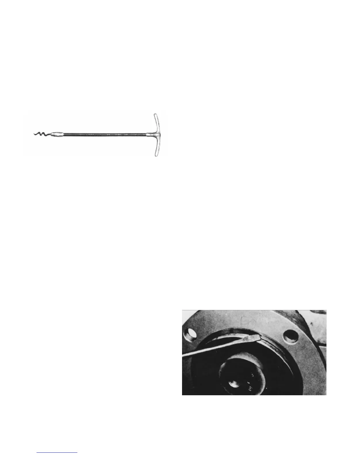
3. Use a pair of packing extractors (Figure 4-2) to remove
four packing rings (22), lantern ring halves (23) and two
additional packing rings (22).
Figure 4-2. Packing Removal Tool
3. Inspect surface of drive shaft for wear or grooves. If
shaft is worn through the chrome plating into the base metal,
or is badly scored or grooved it should be replaced.
4. If drive shaft is not worn, install two rings of packing, the
lantern ring halves, and four more rings of packing; lubrica-
ting them before installation with a good grade of packing
grease. Be sure to stagger the packing ring joints at 90°
increments. (See Section 4-26.)
CAUTION: Always use a proper packing tamper tool to
install packing. Do not use a pointed or sharp
tool, as damage to the packing material or
drive shaft could result. To assure proper
shaft lubrication, never use a one-piece
spiral wrap packing.
5. Replace packing gland (21) and secure with packing
gland nuts. (See fig. 4-1.)
6. Adjust packing per Section 4-3.
4-5. LUBRICATION
4-6. Bearings. The bearings are lubricated at the factory
and will only need to be re-lubricated when the shaft/bearing
assembly is removed from the pump.
4-7. Gear Joints. Both gear joints are packed with lubri-
cant during assembly, and will only need to be re-lubricated
when gear joints are disassembled.
4-8. DISASSEMBLY
Note: The following instructions cover ONE procedure for
disassembling all pump components. Major pump
components can be disassembled in various ways
since specific installation location limitations will
determine method of component removal.
4-9. Disconnect Pump
1. Flush the pump (preferably with clean water) to remove
the pumpage from the unit.
Page 5
2. Shut off pump.
3. Close suction and discharge valves.
4. Turn off flush water to packing or mechanical seal,
if used.
5. Disconnect power source.
6. Drain any fluid in pump by removing the drain plug or
inspection plate.
7. Remove inspection plate (32) and gasket (33).
4-10. Packing Removal
1. Shut off pump.
2. Complete Section 4-9, steps 3 - 6.
3. Remove gland adjustment nuts (F), gland studs (H) and
gland halves (21) from stuffing box.
4. Remove packing rings (22). This is best done by using
flexible packing extractors (see fig. 4-2). Use two extractors
simultaneously on opposite sides of each ring. Pull evenly.
5. Remove lantern rings (23) in similar fashion. Twist split
rings to remove from shaft.
6. Remove additional packing rings.
4-11. Stator Removal
1. Complete Section 4-9.
2. Remove section of discharge pipe attached to dis-
charge flange (37).
3. Remove top half of stator support (31).
4. Unbolt stator clamp ring (36A) from suction housing (29).
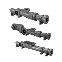
Pull stator off rotor (see note below). Remove stator
gasket (34). Use a screwdriver tip to carefully remove
stator retaining ring (35). (See fig. 4-3.) Remove stator
clamp ring (36) from stator (30).
Figure 4.3. Typical Retaining Ring Removal