TABLE OF CONTENTS
Page
1-1. INTRODUCTION..................................................1
1-2. GENERAL....................................................1
1-3. NAMEPLATE DATA.....................................1
1-4. Pump Rotation ..................................1
1-5. Model Number...................................1
1-6. Frame Size Designation....................1
1-7. Type Designation..............................1
1-8. Trim Code .........................................2
1-9. Variation of Standard Parts...............2
2-1. INSTALLATION...................................................2
2-2. GENERAL....................................................2
2-3. PIPING.........................................................2
2-4. Suction Piping...................................2
2-5. Suction Housing Rotation..................2
2-6. Discharge Piping...............................2
2-7. FOUNDATION ...........................................3
2-8. SHAFT ALIGNMENT .................................3
2-9. On Coupling Connected Units...........3
2-10. On Belt Drive Units ...........................3
2-11. WATER FLUSH OF PACKING ..................3
3-1. OPERATION........................................................4
3-2. INITIAL CHECK...........................................4
3-3. START-UP...................................................4
3-4. PACKING LEAKAGE...................................4
4.1. MAINTENANCE .................................................4
4-2. GENERAL....................................................4
4-3. PACKING ADJUSTMENT............................4
4-4. PACKING REPLACEMENT.........................5
4-5. LUBRICATION.............................................5
4-6. Bearings............................................5
4-7. Gear Joints........................................5
4-8. DISASSEMBLY..........................................5
4-9. Disconnect Pump..............................5
4-10. Packing Removal ..............................5
4-11. Stator Removal .................................5
4-12. Drive End Gear Joint Removal..........6
4-13. Rotor and Connecting Rod
Removal............................................6
4-14. Drive Shaft and Bearings Removal....6
4-15. CLEANING ................................................6
4-16. INSPECTION.............................................7
4-17. Bearings...................................7
4-18. Drive Shaft...............................7
Page
4-19. Seals.......................................................7
4-20. Packing...................................................7
4-21. Rotor.......................................................7
4-22. Stator......................................................7
4-23. All Other Parts ........................................7
4-24. ASSEMBLY..........................................................
4-25. Lubrication During Assembly..................7
4-26. Packing Installation.................................8
4-27. Bearing Housing/Suction
Housing Assembly..................................8
4-28. Bearing/Drive Shaft Assembly................8
4-29. Rotor/Stator Assembly............................9
4-30. Rotor Gear Joint Assembly.....................9
4-31. Rotor/Stator to Drive End
Assembly..............................................10
4-32. Drive End Gear Joint Assembly............10
4-33. Stator Support/Discharge Assembly.....11
4-34. Final Assembly .....................................11
4-35. Packing Adjustment..............................11
4-36. STORAGE.......................................................11
4-37. Short Term Storage..............................11
4-38. Long Term Storage...............................11
4-39. PACKING SPECIFICATION............................12
4-40. VARIATIONS OF STANDARD PARTS...........12
4-41. Rotors...................................................12
4-42. Drive Shafts..........................................12
4-43. STANDARD HARDWARE...............................13
4-44. SELECTING THE CORRECT PART...............14
4-45. PARTS LIST....................................................15
4-46. SHAFT SLEEVE ARRANGEMENT.................24
4-47. Disassembly .........................................24
4-48. Assembly..............................................24
4-49. FIBER DEFLECTOR OPTION..............................
4-50. OPERATION..........................................26
4-51. DISASSEMBLY/ASSEMBLY..................26
4-52. PARTS LIST...........................................26
4-53. FLUSH GLAND OPTION..................................26
4-54. GENERAL..............................................26
4-55. INSTALLATION......................................26
4-56. OPERATION..........................................27
4-57. STANDARD HARDWARE......................28
4-58. PARTS LIST...........................................28
4-59. TROUBLESHOOTING CHART........................29
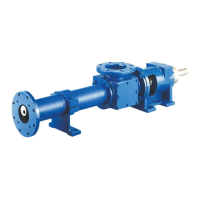
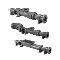
Note: This service manual outlines installation, operation and maintenance procedures
for the flanged “G1” models of the Moyno 2000 pump. For information on the open
throat (G2) and/or the bridge breaker (G3) models of the Moyno 2000 pump, refer
to the G2/G3 Service Manual, or contact your nearest Moyno pump representative.