Page 12
5. See OPERATION Sections 3-1 through 3-4 before
startup. Be sure all lubricants are in good condition.
4-38. Long Term Storage. If pump is to be in storage for
more than 6 months, perform the above short term storage
procedures plus the following:
1. Occasionally rotate the pump manually a few revolu-
tions to avoid a “set” condition of rotor in stator elastomer.
This will prevent hard starting and excessive torque require-
ments when pump is again put into operation.
2. Apply rust inhibitor to all unpainted cast iron and
machined carbon steel surfaces.
3. Remove drive belts if applicable.
4-39. PACKING SPECIFICATION
Standard packing on all Moyno 2000 pumps consists of
braided PTFE fibers impregnated with ultra-fine graphite.
Optional types of packing are available for food, high
temperature and other types of service. Consult your nearest
Moyno representative.
4-40. VARIATIONS OF STANDARD PARTS
The following are variations available for modifying pumps
to meet specialized pumping conditions. If the trim code of
your pump is other than “AAA,” contact your nearest Moyno
representative for clarification. Do not modify your pump with
any variation unless you have determined that it is
compatible with your application.
The three-character trim code is designed as follows. The
first character identifies any sealing variations, the second
character identifies any internal variations, and the third
character identifies any rotor variations.
Sealing Variation
Internal Variation A A A
Rotor Variation
The trim code “AAA” represents a pump with standard fea-
tures. Deviations from standard are to be indicated by
changing the appropriate character from the choices listed.
When two or more letters are combined, dashes are used to
separate the three areas of the trim code for clarity.
SEALING VARIATIONS
A — BRAIDED TEFLON & GRAPHITE PACKING, (Black)
Standard to all lines except Quick Disassembly
pumps. Optional on Quick Disassembly pumps.
C — BRAIDED TEFLON PACKING, (White) Optional
packing on all lines.
D — DOUBLE MECHANICAL SEAL, Optional on all
lines. Not offered on #2 “L” frame.
F — BRAIDED TEFLON FOOD GRADE PACKING,
(White) Standard on all Quick Disassembly pumps.
Optional on all other lines.
G — 100% GRAPHITE PACKING, (Gray) Optional to all
lines.
H — FLUSH PACKING GLAND
S — SINGLE MECHANICAL SEAL, Optional on all lines.
W — WATER FLUSH, Optional on all lines.
X — Special to application
INTERNAL VARIATIONS
A — Standard plated shaft
B — Non-plated shaft
C — Solid drive shaft configuration
E — Extension tube with extended auger
F — Extended drive shaft (for back stop or large pulley)
G — Ceramic coated drive shaft
K — Tungsten carbide coated drive shaft
M — Chromium carbide coated drive shaft
R — Fiber deflector
S — Shaft sleeve
X — Special to application
ROTOR VARIATIONS
A — Standard size with chrome plating
B — Non-plated (no plating)
C — Standard undersize
E — Standard oversize
G — Ceramic coating
K — Tungsten carbide coating
M — Chromium carbide coating
X — Special to application
4-41. Rotors identified on parts listing are standard size
with hard chrome plated surface. Other variations of rotor
size and finish may be ordered by selecting the standard
rotor part number and changing the last digit of the rotor
number as follows:
2 = Standard size, non-plated
3 = Undersize, chrome-plated
4 = Undersize, non-plated
5 = Oversize, chrome-plated
Do not change rotor sizes without consulting your local
Moyno Sales Office. These variations are used for certain
specialized pumping conditions only.
4-42. Drive Shafts shown have hard-chrome plating on the
packing wear area. If non-plated drive shafts are required,
select the standard part number and change the last digit to
next higher number; example: PE0261 to PE0262. If the
optional shaft sleeve is used, refer to Table 4-13 and 4-14 for
appropriate part numbers.
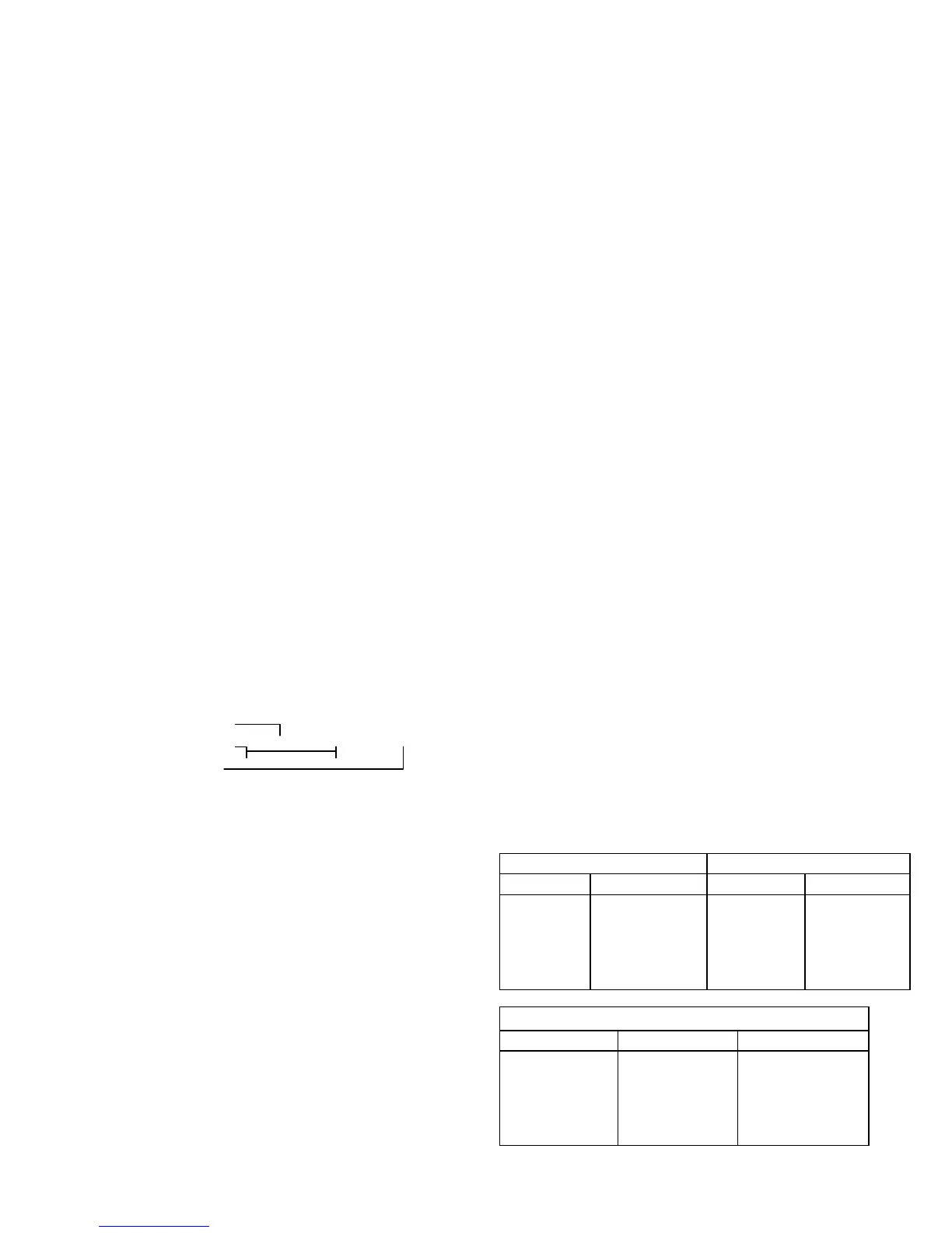
TORQUE GUIDELINES CHART
Stainless Steel Bolts Carbon Steel Bolts
Size Max. Torque Size Max. Torque
N0. 10-24
1/4-20
5/16-18
3/8-16
1/2-13
22.8 in. lb.
75.2 in. lb.
132 in. lb.
236 in. lb.
517 in. lb.
5/16-18
3/8-16
1/2-13
5/8-11
3/4-10
10 ft. lb.
21.7ft. lb.
43.5ft. lb.
86 ft. lb.
152 ft. lb.
Connecting Rod Lock Nuts
Drive End Nut Size Max. Torque
E
F
G,H
J
K
9/16-18
3/4-16
7/8-14
1 1/4-12
11/2-12
25ft.lb.
35 ft. lb.
50ft.Ib.
85 ft. lb.
110 ft. lb.
Note: Torque values are from the Industrial Fasteners In-
stitute and Craftsman Corp.