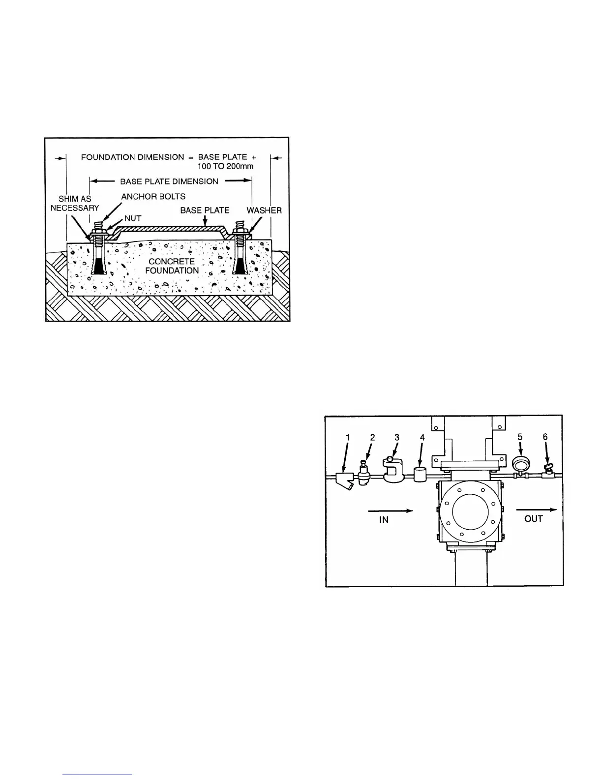
2-7. FOUNDATION
Each unit should be mounted on a strong, fabricated-steel
base plate. The base plate should be mounted on a concrete
foundation. The foundation should be approximately 4” to 8”
longer and wider than the base for which it is built. (See fig.
2-1.) Anchor bolts for the base plate should be located in the
foundation.
Figure 2-1. Typical Foundation Example
Check the base plate surface with a carpenter’s level and
place shims under the base plate at the places necessary to
make it level. Then check the pump, driver shaft and the
pump ports to ensure that they are level. Complete base
mounted units supplied by Moyno including pump and driver
are leveled with respect to the base at the factory. Shifting
may occur during shipment. The pump and driver should be
realigned. Care should be exercised to ensure that all
components are level and mounted in a direct line.
For maximum rigidity and lower noise levels the base
plate should be grouted to the foundation after the anchor
bolts have been evenly tightened. A good grade of non-
shrink grout is recommended. The spaces between the base
plate and the foundation around the shims should also be
filled with grout. Allow the grout to dry according to
manufacturer’s instructions, then fully tighten the anchor
bolts.
2-8. SHAFT ALIGNMENT
Although the base-mounted units supplied by Moyno are
leveled with respect to the base before shipment, most of the
larger pump and driver units are shipped with the flexible
coupling disconnected.
After the base has been bolted down to the foundation,
check the following conditions:
2-9. On coupling connected units, be sure that the pump
and driver shafts are realigned before the coupling is con-
nected. Care should be exercised to ensure that all com-
ponents are level and mounted in a direct line.
Page 3
Check gap between coupling halves (refer to coupling
manufacturers recommendations). Adjustment can usually
be accomplished by loosening the mounting bolts on either
the pump or driver and moving the loosened component into
alignment with the fixed component. On couplings with equal
diameter hubs, it may be possible to lay a straight edge
axially across the coupling halves to check alignment.
2-10. On belt drive units, check to ensure that sheaves or
sprockets are in alignment. Check belts for proper tension.
Tension requirements will vary with type of belt, center
distances, and belt speeds. Consult belt manufacturer for
specific recommendation.
2-11. WATER FLUSH OF PACKING
The packing may be either grease lubricated through a
grease fitting in the stuffing box or have plumbing connected
to the housing to allow for water flushing.
Packing is not grease lubricated at the factory prior to
shipping.
When the material being pumped is abrasive, water
flushing the packing is recommended to extend shaft life.
Clean water can be injected though a 1/8” NPT hole that
normally houses the grease fitting for lubricating the packing.
The water should be permitted to leak axially along the shaft
and be removed from the second tapped hole in the stuffing
box. The discharge from the stuffing box should be throttled
slightly to maintain 10-15 PSI higher pressure in the stuffing
box than is present in the suction housing. (See fig. 2-2.)
Flow rate should be approximately 1/2-2 gpm.
If a mechanical seal is used, consult the seal manufac-
turers’ instructions for seal flush requirements.
Figure 2-2. Typical water flush arrangement for units
with packing includes strainer valve (1), pressure
regulating valve (2), sight flow meter (3), solenoid
valve (4), pressure gauge (5), and needle valve (6).